In the current landscape of hyper-connectivity, the Fiber Optic Splitter has transcended its role as a simple hardware component. As we push toward widespread 50G-PON deployments and the integration of AI-driven edge computing, these passive devices are the gatekeepers of network scalability.
For ISP architects and data center engineers, the choice of splitting technology is no longer just about cost—it’s about link budget management and long-term spectral efficiency.
The Architecture of Distribution: PLC vs. FBT in the 10G+ Era
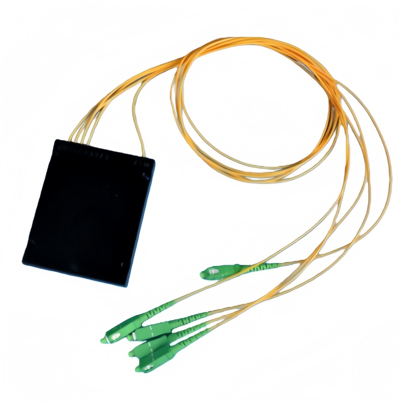
While Fused Biconical Taper (FBT) splitters still hold a niche in low-cost, simple monitoring links (where 1×2 or asymmetrical ratios like 90/10 are required), Planar Lightwave Circuit (PLC) technology is the undisputed backbone of modern FTTx.
The demand for 2026 is driven by Uniformity. In a multi-gigabit environment, a deviation of even 1.5dB across output ports can lead to “optical path disparity,” causing some ONTs (Optical Network Terminals) to struggle with signal-to-noise ratios while others thrive.
Table 1: Comparative Engineering Specifications (2026 Standards)
| Parameter | PLC Splitter (Premium Grade) | FBT Splitter (Standard) |
| Spectral Range | 1260nm – 1650nm (Full Band) | 1310/1490/1550nm (Narrow Band) |
| Max Split Ratio | 1:128 (Single Chip) | 1:4 (Cascaded) |
| Temperature Stability | $-40^{\circ}\text{C}$ to $+85^{\circ}\text{C}$ | $-5^{\circ}\text{C}$ to $+75^{\circ}\text{C}$ |
| PDL (Polarization Dependent Loss) | $< 0.2\text{ dB}$ | $> 0.4\text{ dB}$ |
| Typical Application | GPON, XGS-PON, 50G-PON | CATV, Localized Monitoring |
The Economics of Insertion Loss: Why 0.1dB Matters
In 2026, the industry has shifted toward Lower Loss “Grade A” PLC Splitters. Why? Because as we move from GPON to XGS-PON and eventually 50G-PON, the optical power budget becomes tighter.
Every decibel saved in the passive distribution network (ODN) allows for an extra 2–3 kilometers of reach or the inclusion of an extra mechanical splice without breaching the sensitivity threshold of the receiver.
Table 2: PLC Splitter Insertion Loss Budget (G.657.A1 Fiber)
| Split Configuration | Typical Loss (dB) | Max IL (Premium) | Max IL (Standard) |
| 1:8 | 9.8 | 10.2 | 10.7 |
| 1:16 | 13.1 | 13.5 | 14.1 |
| 1:32 | 16.2 | 16.5 | 17.2 |
| 1:64 | 19.5 | 20.1 | 21.0 |
Note: Calculations include connector loss (SC/APC) based on 2026 manufacturing tolerances.
Critical Trends: Packaging for High-Density Deployments
The physical form factor is evolving to meet the “Space-is-Money” reality of modern data centers:
- Micro-Plug-in (Mini) Splitters: Essential for high-density splice closures. With the rise of Air-Blown Fiber, these 4mm steel tube splitters are being integrated directly into micro-duct manifolds.
- High-Density LGX Modules: For Central Office (CO) environments, we are seeing a move toward ultra-high-density (UHD) cassettes that house four 1:32 splitters in a single 1U rack space.
- Non-Uniform PLC Splitters: A burgeoning trend in “Bus-Topology” rural fiber builds, allowing for different percentages of light to be “dropped” at various points along a single fiber strand, mimicking the efficiency of FBT but with the stability of PLC.
Professional Insights: Best Practices for 2026
- Standardize on SC/APC: Unless there is a legacy reason, SC/APC (Green) is mandatory. The $8^{\circ}$ angle-polish provides a return loss of $>60\text{dB}$, which is vital to prevent back-reflections from damaging high-power 50G-PON transmitters.
- Wavelength Future-Proofing: Ensure all splitters are tested for the 1650nm window. This is the “maintenance wavelength” used by OTDRs (Optical Time Domain Reflectometers) for in-service troubleshooting.
- Environmental Testing: For OSP (Outside Plant) deployments, always verify that the splitter meets Telcordia GR-1209/1221 standards for moisture and thermal cycling.
Industry FAQ: Technical Deep Dive
Q1: How does the split ratio affect the maximum distance of a GPON/XGS-PON branch?
A: In a standard 28dB power budget, a 1:32 split consumes approximately 17dB. After accounting for fiber attenuation ($0.35\text{dB/km}$ at 1310nm) and safety margins, this typically limits the physical reach to 20km. Moving to a 1:64 split usually requires an “Extended Class” optics module (B+ or C+).
Q2: Can PLC splitters handle high-power Raman amplification?
A: Standard PLC splitters are rated for roughly $500\text{mW}$ of optical power. If your network utilizes high-power Raman amplifiers for long-haul transmission, you must specify “High-Power Resistance” splitters to avoid core-burning at the input pigtail.
Q3: What is the impact of PDL (Polarization Dependent Loss) on 10G+ signals?
A: High PDL causes fluctuations in the received signal strength as the polarization state of the light changes over time. In 10G and 50G systems, this manifests as increased Jitter and Bit Error Rate (BER). Premium splitters keep PDL under $0.2\text{dB}$ to ensure “Rock-Solid” data integrity.