
An MPO to LC breakout cable looks like the simplest line item in a 40G or 100G bill of materials: one MPO connector at the switch end and a set of LC duplex legs at the panel end. It is also the line item most often re-ordered, because the fiber count, polarity and gender the link actually needs were decided long before anyone opened the box. Order the wrong variant and every leg on the link hands transmit to transmit, and the only fix is a week of waiting for a new shipment.
Where a Breakout Cable Fits in the Structured Link
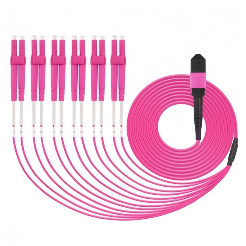
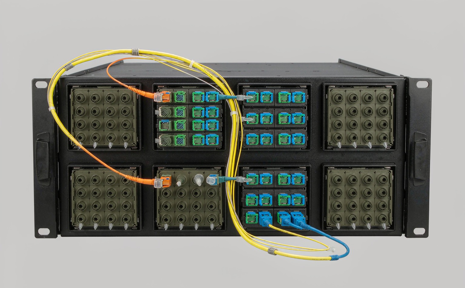
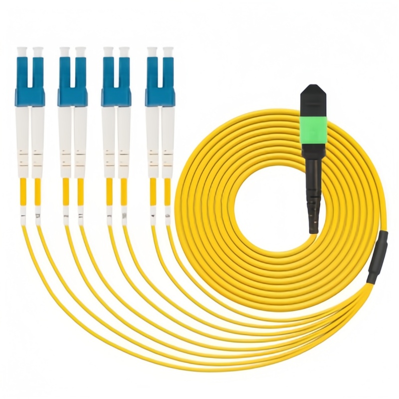
A breakout cable, sometimes called a fan-out assembly, splits one multi-fiber MPO interface into several duplex LC interfaces. It sits at the point where parallel optics meet single-channel equipment: the switch side speaks 8-fiber parallel (SR4 transceivers), the server or access side speaks duplex LC. The MPO MTP trunk cable carries the backbone between distribution areas, an adapter panel or cassette presents the MPO interface, and the breakout converts it down to LC ports that ordinary patch cords can reach.
Two deployment patterns cover most projects. In the direct-attach pattern, the breakout plugs straight into the QSFP+ or QSFP28 transceiver and its LC legs land on a small LC panel in the same rack. In the cassette pattern, the trunk terminates in a cassette in the main distribution area and short breakouts patch between panels. The direct pattern minimizes connectors and loss; the cassette pattern makes future moves-adds-changes cheaper because the expensive part, the long trunk, is never disturbed. Both need the breakout specified against the same three parameters: fiber count, polarity and gender.
Fiber Count: 8, 12, 16 or 24 Fibers
The transceiver decides the count. A 40G QSFP+ SR4 or 100G QSFP28 SR4 module transmits on four fibers and receives on four, so an 8-fiber breakout is the tightest match. A 12-fiber breakout remains the industry default, however, because it matches the installed base of 12-fiber trunks and cassettes and leaves four fibers unused or reserved. Single-mode 100G DR4 and 200G/400G SR8 variants also use eight fibers, while 24-fiber breakouts serve high-density breakout fields carrying three parallel 8-fiber links through one connector. The table below maps the common cases.
| MPO fiber count | LC duplex legs | جهاز إرسال واستقبال نموذجي | Typical link |
|---|---|---|---|
| 8-fiber | 4 duplex | 40G QSFP+ SR4 / 100G QSFP28 SR4 | 4 x 10G or 4 x 25G |
| 12-fiber | 6 duplex (4 used) | 100G QSFP28 SR4 on 12-fiber plant | 4 x 25G, 2 legs spare |
| 12-fiber | 6 duplex (6 used) | Legacy 12-fiber duplex links | 6 duplex channels |
| 16-fiber | 8 duplex (4 used) | 400G SR8 / DR4 on 16-fiber plant | 4 x 100G or 4 x 50G |
| 24-fiber | 12 duplex | Density consolidation | 3 x 8-fiber parallel links |
When the link is single-mode, the unused fiber positions still matter for polarity on some systems, so order the count the system was designed around rather than “the closest”. A 100G DR4 link through a 12-fiber APC breakout, for example, conventionally uses positions 1-4 and 9-12 with the middle four dark. Keep that convention consistent across every rack, or the next technician will spend an afternoon tracing dark fibers.
Polarity: Match the Breakout to the Link Method
Polarity is where breakout cables go wrong most often. TIA-568.3-D defines three polarity methods for MPO channels, and the breakout has to agree with the method the rest of the channel uses. If the trunk and cassette already provide the Tx/Rx crossover, the breakout must be straight-through; if the breakout itself must provide the crossover, the trunk must be straight-through. Mixing the two leaves transmit talking to transmit on every leg. Our earlier guide to MPO polarity methods A, B and C covers the channel-level logic; the breakout-level summary is shorter.
| Breakout polarity | Fiber mapping | في مكانه الصحيح |
|---|---|---|
| Type A (straight) | Position 1 to position 1 through | Cassette-based Method A channels, where the cassette performs the flip |
| Type B (flipped) | Tx and Rx crossed at the LC end | Direct QSFP+ / QSFP28 SR4 to 4 x 10G/25G breakout, the most common configuration |
| Type C (pair-flipped) | Adjacent pairs swapped | Rare; legacy installations only |
A safe default for a switch-to-panel breakout carrying parallel optics is Type B; a safe default for a breakout patching between two panel positions inside a Method A cassette system is Type A. Confirm against the cassette or panel datasheet before the order is placed, and write the polarity type on the purchase order line itself.
Gender, Guide Pins and Adapter Selection
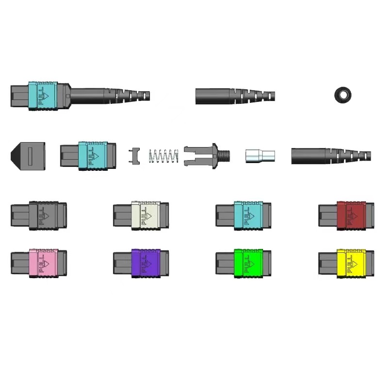
MPO connectors are male (with guide pins) or female (without). Two males will not mate; two females mate but leave nothing to align the ferrules, so alignment loss destroys the link budget. The rule at a panel is simple: the adapter carries the split sleeve, one side male and one side female. Transceiver receptacles contain their own alignment hardware and accept female MPO plugs, which is why switch-attached breakouts are almost always female at the MPO end. Panel-to-panel breakouts take whatever gender the adapter pair requires. The محول الألياف البصرية selected for the panel must match that gender plan and the ferrule polish, and US Conec publishes the MTP connector reference that most vendors work from.
Fiber Grade and Reach
Multimode breakouts come in OM3, OM4 and OM5; single-mode comes as OS2 to ITU-T G.652.D or, for tight trays and short legs near equipment, bend-insensitive G.657.A1. Under the IEEE 802.3 Ethernet specifications, 40GBASE-SR4 reaches 100 m on OM3 and 150 m on OM4, while 100GBASE-SR4 reaches 70 m on OM3 and 100 m on OM4, so the grade is set by the longest run in the channel, not the average. OM5 adds no reach for SR4 optics but supports shortwave wavelength-division optics later, which can matter for a building that will not be re-cabled for a decade. On the single-mode side, 100GBASE-DR4 reaches 500 m over G.652.D, and the توصية ITU-T G.652 defines the fiber the transceiver vendors design against.
Jacket color follows the grade, and it is worth enforcing at the panel: aqua for OM3, magenta for OM4, lime for OM5, yellow for OS2. A rack where all four appear should never show a beige adapter holding an OS2 leg, because the next move-add-change will trust the color and plug a multimode transceiver into a single-mode leg.
Fan-out Length, Stagger and Jacket
The fan-out region is where breakout quality shows. Legs are supplied with equal lengths or staggered, with the longest legs furthest from the MPO so the bundle dresses flat against the panel. Staggered legs cost slightly more and save real minutes on every installation, because the technician does not have to coil six equal legs into a vertical manager to make them all reach. Specify leg length from the measured route: panel depth, plus the vertical manager path, plus roughly 30 cm of service loop per end, exactly as for any other patch cord.
Jacket follows the environment. LSZH for enclosed data center and telecom rooms, OFNP plenum where codes require it, and a 2.0 mm leg for dense panels where 3.0 mm bundles will not close. Bend radius discipline still applies in the fan-out region: ten times outer diameter in service, twenty times while pulling, regardless of how short the leg is.
Loss Limits and Acceptance Testing
A breakout adds one MPO connection and one LC connection per leg, so its loss budget is the sum of the two. Factory test reports should quote insertion loss and return loss per fiber, not per cable, and the acceptance limits should be agreed before delivery. The limits below reflect common commercial grades; the متجر IEC الإلكتروني holds the measurement methods behind them.
| المعلمة | Standard grade | Low-loss grade | أساس الاختبار |
|---|---|---|---|
| MPO insertion loss (per fiber) | ≤ 0.75 dB | ≤ 0.35 dB | IEC 61300 series injection techniques |
| LC insertion loss (per fiber) | ≤ 0.30 dB | ≤ 0.15 dB | IEC 61300-3-4 |
| MPO return loss, multimode | ≥ 20 dB | ≥ 25 dB | IEC 61300-3-6 |
| LC return loss, single-mode APC | ≥ 60 dB | ≥ 65 dB | IEC 61300-3-6 |
| End-face geometry and cleanliness | Inspected per IEC 61300-3-35 criteria before packing | IEC 61300-3-35 | |
On receipt, inspect the MPO end and a sample of LC legs with a scope before anything is plugged in, then run an insertion-loss check on every leg with a light source and power meter, matching fiber to fiber. An assembly that passes the factory report but fails on site usually has a contaminated MPO end; clean and retest before blaming the cable.
Decision Tree: Five Questions Before You Order
- How many fibers does the transceiver use? 8-fiber parallel optics on an 8-fiber or 12-fiber plant, 16-fiber for SR8/DR4 upgrades, 24-fiber only for consolidation fields.
- Who performs the Tx/Rx flip? If the cassette does, order Type A; if the breakout must, order Type B. Never both and never neither.
- What gender does each end need? Female into transceivers; at adapters, male opposite female, fixed in writing on the PO.
- Which grade and reach? OM4 for 100 m at 100G, OS2 G.652.D for DR4, G.657.A1 only where the route bends tightly.
- Which loss grade does the budget allow? Standard grades fit most short channels; low-loss grades belong in long channels and high-count breakouts where every decibel is shared.
Send Fenxi your transceiver list, panel layout and channel lengths, and we will return a quotation covering MPO trunk and breakout assemblies, LC connectors and legs, و إطارات توزيع الألياف البصرية ODF they terminate on, with polarity and gender written against each line item.