
Specify LC duplex polarity by the end-to-end transmit and receive mapping, then use clip orientation and connector labels to preserve that mapping. “A-to-B” or “A-to-A” written without a port diagram is not enough when uniboots, removable clips, cassettes or equipment-specific transceiver layouts are involved.
LC duplex assemblies are simple until one end is flipped in the field, a clip is replaced, or a cassette introduces another polarity transformation. A buyer should freeze the channel map on the drawing, mark both ends, and verify continuity on the finished assembly. The physical clip is part of that control, but it is not the complete definition.
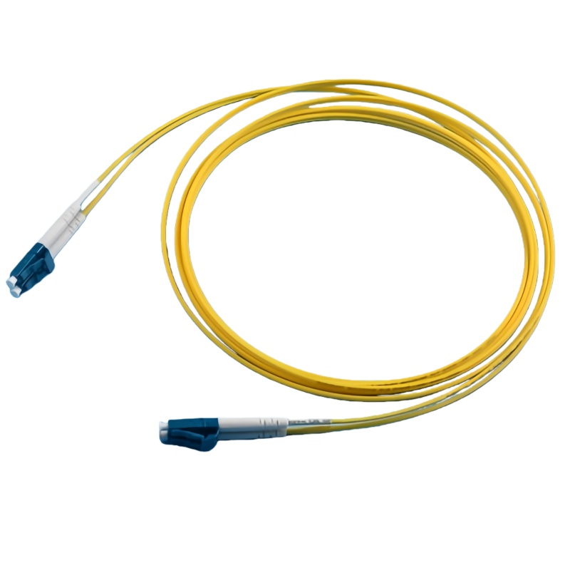
What Do A-to-B and A-to-A Mean on an LC Duplex Cord?
The names describe how the two fibre positions map between ends. The drawing should show port 1 and port 2 at both ends and define the viewing direction, because a front view and a cable-side view can make the same assembly look reversed.
| Polarity notation | End-to-end map | Common use | Drawing requirement |
|---|---|---|---|
| A-to-B | Position 1 at one end reaches position 2 at the other | Duplex transmit-to-receive crossover where equipment ports expect the pair reversed | Show both connector faces and fibre identities |
| A-to-A | Position 1 reaches position 1 and position 2 reaches position 2 | Straight-through segments where crossover occurs elsewhere | Identify where the channel is crossed in the full link |
| Field-reversible clip | Technician can change the pair orientation | Sites that need controlled polarity changes during deployment | State approved clip positions and label rule |
| Uniboot construction | Both fibres share one cable body and may use a switchable connector head | Dense patching with reduced cable volume | State the switch procedure and accepted final map |
| Cassette channel | Cord polarity interacts with trunk and cassette mapping | Structured cabling systems | Provide an end-to-end channel schedule, not a cord-only note |
How Do You Prevent Polarity Errors in Production and Installation?
Use independent controls for assembly, labelling and verification. If every control relies on clip colour or technician memory, one replacement part can reverse the channel.
Define the viewing direction
Place connector face diagrams on the assembly drawing and state whether the view is looking into the plug or from the cable side. Number both fibre positions and carry those identifiers through the bill of materials and test sheet.
Mark both ends
Use durable A/B or Tx/Rx labels that remain readable after routing. Colour can support identification, but colour alone is weak because clips and boots can be exchanged during maintenance.
Verify continuity on the finished cord
A visual check of the clip does not prove the fibre map inside a uniboot or a reworked connector. Record end-to-end continuity by fibre identity after final assembly and before packaging.
Test the complete channel
For a cassette-based link, verify trunk, cassette and patch cords together. The correct cord can still produce a reversed channel when another module applies the same crossover a second time.
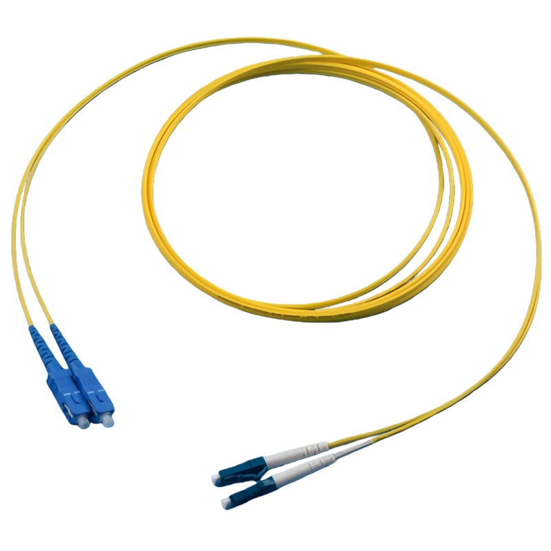
Polarity Failure Modes at Handover
A link that is optically clean can still be dark because the transmitter reaches another transmitter. Keep continuity and optical loss as separate acceptance results.
| Symptom | Mögliche Ursache | Field check | Permanent control |
|---|---|---|---|
| Both power readings look plausible but link stays down | Transmit and receive are reversed | Trace fibre identity end to end | Approved channel map and continuity report |
| Link fails after clip replacement | Clip reinstalled in the wrong orientation | Compare face view to drawing | Keyed work instruction and labels on both ends |
| Only one cassette path fails | Cassette and cord apply conflicting polarity | Bypass sections and test continuity | System-level polarity schedule |
| Technicians disagree on A and B | Viewing direction was never defined | Use connector-face diagram | Drawing convention stated in title block |
| Replacement cord reverses the channel | Supplier used a different default construction | Check serialized continuity record | Put map and revision on the purchase order |
Standards und Belege zur Untermauerung der Bestellung
Diese IEC-Veröffentlichung legt die Standardabmessungen für die Schnittstellen der LC-Steckverbinderfamilie fest. Siehe IEC 61754-20 – Norm für die LC-Schnittstelle.
Die Ausgabe von 2024 regelt die Prüfung und Testung von installierten Glasfaserkabeln. Siehe ISO/IEC 14763-3:2024 – Prüfung von optischen Verkabelungen.
FOA explains reference cords for insertion-loss and OTDR measurements and the need to match fibre type and connector interfaces. See FOA reference-cable guide.
LC Duplex Field Checklist
Polarity is a path property. Control the connector clip, but release the assembly against a labelled end-to-end map and verify the installed channel after cassettes and trunks are included.
- Show connector faces and viewing direction on the drawing
- Number both fibres and label both cable ends
- Record finished-cord continuity by fibre identity
- Define approved positions for reversible clips or uniboot heads
- Verify the complete installed channel before service activation
Für ein projektspezifisches Angebot sehen Sie sich bitte das Angebot von Fenxi an LC-Steckverbinder-Sortiment, LC simplex connectors, LC duplex connectors, und LC high-density deployment guide. Bitte geben Sie den Zielmarkt, die Anschlussschnittstellen, den Fasertyp, den Kabelaufbau, die Stückzahlen, die Zeichnungsversion und die erforderlichen Prüfprotokolle an. In der Antwort werden dann die Standardoptionen aus dem Katalog von den Artikeln unterschieden, die einer Bestätigung bedürfen oder für die Sonderwerkzeuge erforderlich sind.