
A single mismatch in a fiber optic pigtail order can stall a whole splice day. The buffer arrives at 2.0 mm instead of 0.9 mm, the polish is UPC where the OLT port needs APC, or the bundle is too short for the routing path inside the tray. Because a pigtail is spliced once and then sealed inside an enclosure, a wrong specification is not a quick swap — it is a re-splice, a re-test and often a second truck roll. Four decisions cover almost every order: fiber and buffer, connector and polish, color sequence, and length.
Pigtail, Patch Cord, or Field Connector
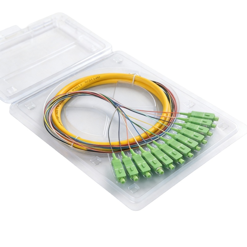
The three options solve different problems, and choosing the wrong one usually shows up as rework months later. A fiber optic pigtail has one factory-polished connector and one bare end that is fusion spliced to the incoming cable. It is a permanent joint that stays inside an ODF, a splice closure or a terminal box. A patch cord carries connectors at both ends and is meant for ports you will re-plug. A field-installable connector is crimped onto a stripped fiber on site and needs no fusion splicer, which makes it useful for emergency restoration and drop work where no splicer is on the van.
| Option | Connector ends | Typical added loss | Ideal para | Rework risk |
|---|---|---|---|---|
| Fiber optic pigtail | One factory connector, one bare end | 0.10–0.20 dB (splice + connector) | Permanent termination in ODF, closure, terminal box | Low once spliced and dressed |
| Patch cord | Connectors on both ends | 0.20–0.35 dB per mated pair | Equipment links, cross-connects, daily moves | Low; unplug and re-patch |
| Field-installable connector | One field connector, no splicer | 0.30–0.50 dB | Fast repair, no-splicer drop work | Higher; depends on operator skill |
These are planning values, not acceptance limits. Confirm them against the product datasheet, your system loss budget and the operator’s acceptance rules before sign-off. The FOA loss budget reference is a practical place to build that budget from the ground up.
Fiber Type and Buffer Construction
Most single-mode pigtails are built on G.652.D or G.657 fiber. G.652.D is the default for duct routes and long-haul plant. G.657.A1 and G.657.A2 are bend-insensitive grades; A2 tolerates a 7.5 mm minimum bend radius against 30 mm for G.652.D, which matters when twelve fibers have to be dressed into a compact FTTH box. The Recomendación UIT-T G.652 defines the base single-mode fiber, and both families splice to each other without correction.
Multimode pigtails follow the same logic with different fiber grades. OM3 and OM4 laser-optimized 50/125 fiber serve enterprise backbones and data center links at 10G through 100G, and OM5 adds wideband support for short-wave division multiplexing. Match the pigtail grade to the installed cable plant and to the transceiver wavelength. Mixing OM1 62.5/125 with OM4 in one channel adds loss the budget never planned for.
Buffer diameter is the dimension buyers forget most often. 250 µm coated fiber is what comes out of a loose-tube cable and works when the pigtail lands straight into a tray holder. 900 µm tight-buffered fiber is the practical choice for most field work: it survives handling, fits standard 60 mm splice sleeves and holds its shape in the tray. A 2.0 mm or 3.0 mm jacketed pigtail is difficult to route inside a 30 mm tray radius and is rarely worth the extra material cost.
Connector Type and Polish
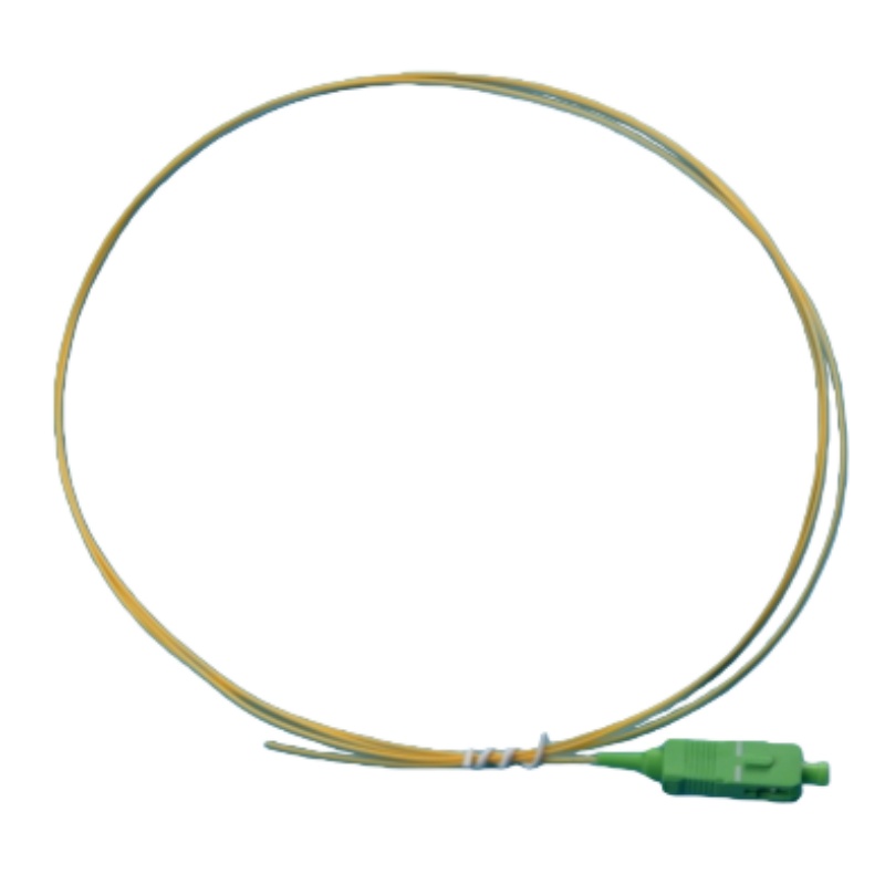
SC/APC is the default for FTTH and PON, LC/UPC for data center frames and high-density ODF, and FC/APC or FC/UPC for test instruments and high-vibration sites. Match the polish to the port. APC connectors are green with an 8° angled end face and return 60 dB or better; UPC is blue at 50 dB or better. Mating UPC to APC damages both end faces and will not hold specification. The FOA connector identification page covers the visual cues for each family.
Order simplex pigtails unless the equipment genuinely needs a duplex clip. Simplex units route more cleanly in a tray, and a clip can be added at the adapter side in seconds. Where a project mixes 1.25 mm LC and 2.5 mm SC in the same frame, order hybrid adapter strips rather than asking the field team to improvise: every extra mating interface adds loss and gives you another end face to inspect.
Ask what the connector was tested against. Factory-terminated pigtails are qualified to IEC 61753-1 for optical performance and IEC 61754 for interface dimensions, with GR-326 covering single-mode connector reliability. End-face geometry is checked to IEC 61300-3-35, which is also the pass/fail reference used during inspection, and the interface requirements sit inside TIA-568.3-D for premises cabling.
The 12-Color Code and Bundle Counts
Pigtails ship in 6, 12 and 24-fiber bundles, and the sequence is not decorative. TIA-598-D fixes the order so a technician at the far end of a link can map ports without a tone set. Order positions 1–12 in the standard sequence; positions 13–24 repeat the same colors with a black tracer.
| Position | Color | Position | Color (with black tracer) |
|---|---|---|---|
| 1 | Azul | 13 | Azul |
| 2 | Naranja | 14 | Naranja |
| 3 | Verde | 15 | Verde |
| 4 | Brown | 16 | Brown |
| 5 | Slate | 17 | Slate |
| 6 | White | 18 | White |
| 7 | Red | 19 | Red |
| 8 | Black | 20 | Black |
| 9 | Amarillo | 21 | Amarillo |
| 10 | Violet | 22 | Violet |
| 11 | Rose | 23 | Rose |
| 12 | Aqua | 24 | Aqua |
If your panel is laid out in 12-port groups, order one bundle per group rather than loose singles. Bundles arrive in sequence, which removes the most common source of crossed ports. The 12-core fiber pigtail range covers the standard configurations for SC, LC, FC and ST.
A freshly spliced connector is not automatically clean. Dust on the end face is the leading cause of a failed acceptance test, and Fluke Networks’ fiber inspection guidance sets out what to look for under a scope before you plug in.
Length, Bend Radius and Tray Fit
Length is the specification most often trimmed to save cost, and it is the one that causes the most trouble in the tray. A 1 m pigtail will not reach around the routing path of a 72-core ODF frame. For ODF and closure work, 1.5 m to 2 m is the safe default; 1 m suits a small FTTH box; 3 m is worth paying for where the enclosure sits far from the splice point. Always leave one full slack loop so the tray can be opened for re-work without pulling on a splice.
Keep 0.9 mm fiber at a 30 mm minimum bend radius under load, and check that the tray is rated for the sleeve count you plan to put in it. Overfilling is a quiet problem: the lid presses on the sleeves, microbends appear, and loss climbs over the following weeks. Match the pigtail count to the right bandeja de empalme de fibra óptica capacity from the start rather than after the first tray is full.
Where Pigtails Get Installed
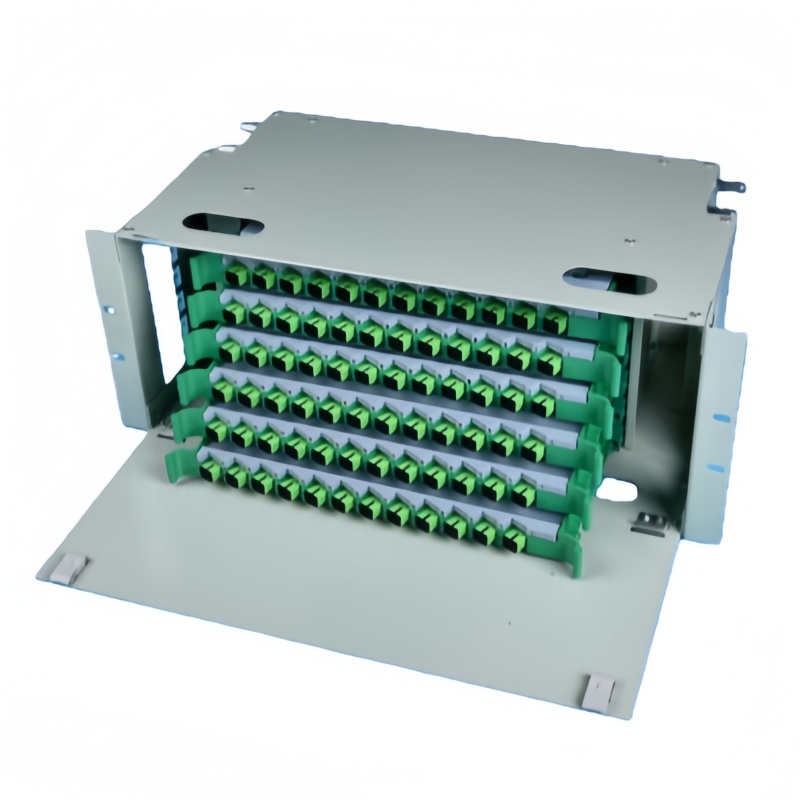
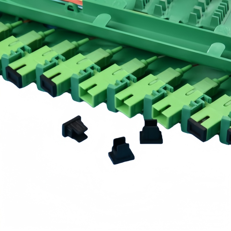
In a rack-mount ODF, pigtails turn a 12 to 144-core trunk into adapter ports on the front plate. In a wall-mounted caja de terminación de fibra, a 4 to 24-fiber bundle does the same job at a building entry or floor distributor. The connector plugs into a matching adaptador de fibra óptica, which presents the port to the patch cord side. That is the whole purpose of the pigtail: it converts a permanent splice into a re-pluggable port you can patch, test and re-route without touching the splice.
Outdoor closures and FTTA cabinets add two constraints the indoor specification does not cover: temperature range and water ingress. Confirm the operating range covers the local extremes instead of the standard -10 °C to +60 °C indoor band, and specify LSZH jacketing where the route passes through occupied space. A pigtail jacket that cracks in a sealed cabinet is the kind of saving that turns into a repeat visit.
Common Pigtail Problems on Site
Most field failures trace back to one of six causes. Working through this list during commissioning is faster than re-testing a whole tray.
| Síntoma | Causa probable | Arreglar |
|---|---|---|
| OTDR shows a 0.5 dB event at the tray | Fiber not seated in the V-groove, or contamination before splicing | Re-cleave, clean with 99.9% isopropyl alcohol, re-splice |
| Return loss fails on an APC link | UPC pigtail mated to an APC port, or mixed polish in one adapter | Match polish to the port; green for APC, blue for UPC |
| Buffer cracks at the tray entry | Bend radius under 30 mm on 0.9 mm fiber | Route a full loop, or move to G.657.A2 fiber |
| Tray lid will not close | Pigtail too short for the routing path, or 2.0 mm cable substituted | Specify 1.5–2 m and keep the 0.9 mm buffer |
| Port mapping wrong after splicing | Color sequence not followed | Follow TIA-598-D order and label both ends |
| Loss climbs a few weeks later | Overfilled tray pressing on sleeves | Re-splice into a tray rated for the sleeve count |
Send connector type, polish, fiber grade, buffer diameter, length and quantity with your enquiry and the returned specification will be project-ready the first time.