A fiber optic splice tray is designed to protect the stripped, vulnerable fiber and the fusion splice point. However, its primary technical function is bend radius protection. In high-speed protocols like XGS-PON or Terabit Ethernet, even a slight macro-bend in a splice tray can induce enough decibel loss to cause intermittent CRC errors or total link failure.
Critical Features of 2026 High-Density Trays:
- Modular Stackability: Integrated hinges that allow trays to flip up without disturbing the “live” fibers in the trays below.
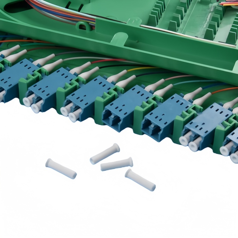
- Ribbon vs. Single Fiber Compatibility: Modern trays now feature interchangeable splice holders to accommodate both 12-fiber ribbons and individual 250μm/900μm fibers.
- UL 94-V0 Flame Retardancy: Now a mandatory standard for indoor data center deployments to prevent fire propagation.
Technical Specifications: Comparing Tray Architectures
Choosing the right tray depends on your environment—whether it’s a ruggedized OSP (Outside Plant) closure or a temperature-controlled ISP rack.
Table 1: Splice Tray Material and Capacity Standards (2026)
| Feature | ABS/Polycarbonate (Standard) | Aluminum/Metal (Industrial) | High-Density Modular (Data Center) |
| Max Capacity | 12 – 24 Cores | 24 – 48 Cores | Up to 144 Cores (Ribbon) |
| Durability | High (Impact Resistant) | Extreme (Heat/Corrosion) | Moderate (Space Optimized) |
| Mounting | Snap-on / Center Hole | Bolt-down | Slide-rail / Hinged |
| Typical Use | FTTx Distribution Boxes | Harsh Industrial/Submarine | Hyperscale Data Centers |
Managing the Loss Budget: Splice Protection Factors
The splice tray is where the Heat Shrink Protection Sleeve lives. If the tray’s groove is not precision-engineered, the sleeve can shift, putting stress on the fusion point. In 2026, engineers are increasingly looking at the Pigtail Management Zone within the tray to ensure that the transition from the buffer tube to the splice is seamless.
Table 2: Environmental and Mechanical Tolerances (Telcordia GR-769)
| Parameter | Specification Requirement | Impact on Signal |
| Minimum Bend Radius | $\geq 30\text{ mm}$ | Prevents macro-bend loss ($<0.05\text{dB}$) |
| Temp Cycling | $-40^{\circ}\text{C}$ to $+75^{\circ}\text{C}$ | Prevents plastic contraction/fiber pinching |
| Crush Resistance | $> 500\text{ N}$ | Protects splices from external mechanical stress |
| Chemical Resistance | Resistant to Re-entry Gels | Prevents tray degradation in OSP closures |
Pro-Tips for Fiber Management in 2026
- Labeling at the Tray Level: Use RFID-embedded labels or QR codes on the tray cover. This allows technicians to scan the tray and instantly see the “Splice Map” (which input fiber connects to which output pigtail) via an AR app.
- Ribbon Fiber Transition: When using 12-fiber ribbons, ensure your tray has a “fan-out” area if you intend to transition to single-fiber LC connectors.
- Color Coding: Follow the TIA-598-D standard religiously. In a tray containing 24 splices, a mistake in the color-coding sequence of the heat-shrink sleeves can lead to hours of troubleshooting during a “midnight cutover.”
Expert Q&A: Fiber Splice Trays
Q: Can I mix 62.5μm (OM1) and 50μm (OM4) splices in the same tray?
A: Physically, yes. Logically, no. While the tray will hold them, the mismatched core sizes will cause massive insertion loss (up to $4\text{dB}$) in one direction. Always segregate different fiber types into separate trays and label them clearly to prevent future technician error.
Q: Why are clear plastic covers preferred for splice trays?
A: Visual inspection is the first line of defense. A clear cover allows a technician to use a Visual Fault Locator (VFL) to see the “red glow” of a broken fiber or a bad splice without opening the tray and risking mechanical damage to the surrounding fibers.
Q: How do you handle “overlength” (slack) fiber in a small tray?
A: The “Figure-8” method is dead. Modern trays use a circular routing path. Always maintain at least two full loops of slack within the tray to allow for at least two re-splicing attempts if the first fusion fails.