
A purchase order that reads “24-fiber single-mode cable” is not a specification. Three suppliers can answer it with three different products and each can claim compliance: a central loose tube duct cable, a stranded multi-tube armored cable and a tight-buffered indoor distribution cable. The glass inside all three may be the same G.652.D. What changes is how that glass is held, and that choice decides whether water reaches the fiber in year five, whether the cable survives a 400 m duct pull, how many hours the splicing crew spends at each enclosure, and whether the authority having jurisdiction lets the run stay inside the building.
The volume behind those decisions is climbing again. CRU figures cited in 2026 sector research put global fiber-to-the-home penetration at 30.4 % in 2025 and 41.1 % by 2027, and the Fiber Broadband Association reported that United States providers passed another 11.8 million homes in 2025, taking FTTH coverage to 98.3 million homes with roughly 60 million first-round opportunities still open. At that volume a construction mistake is not only a technical problem, it is a re-order and a slipped turn-up date.
What Is the Difference Between Loose Tube and Tight-Buffered Cable?
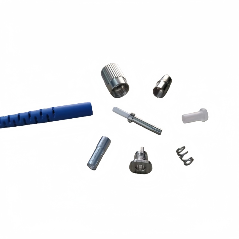
Loose tube cable lets each fiber float inside a protective tube; tight-buffered cable bonds a 900 µm coating directly onto the fiber. Every practical difference between the two follows from that single choice.
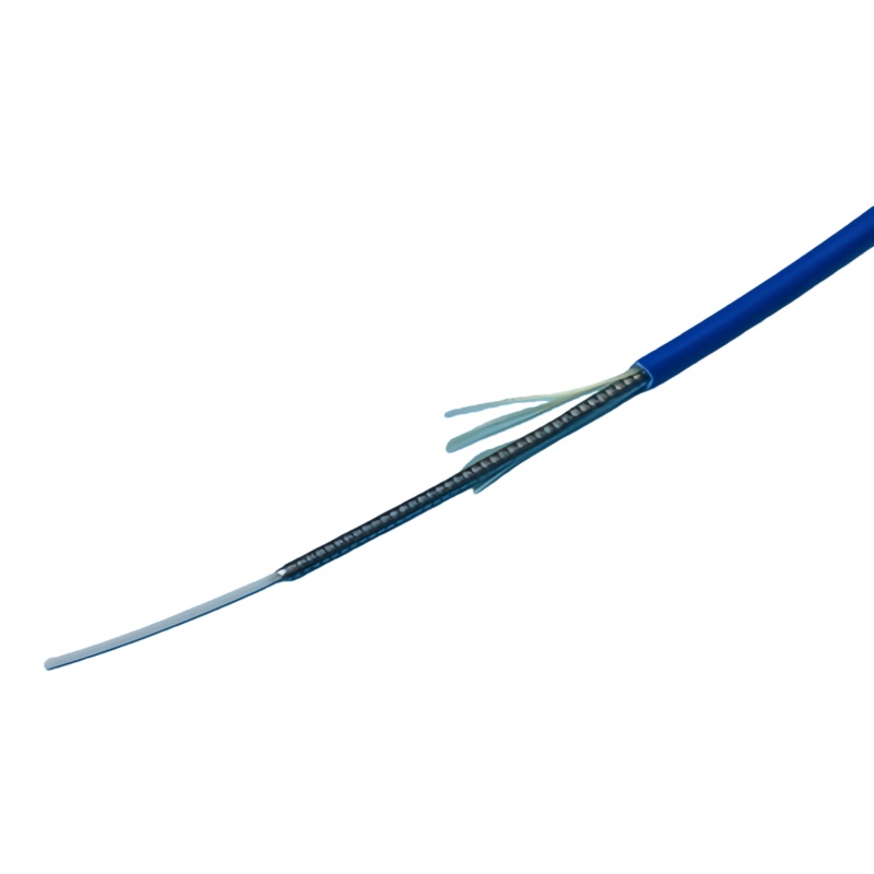
In a loose tube cable the fiber carries only its 250 µm primary coating and sits in a tube with deliberate clearance. The tube is longer than the fiber by a small margin, quoted as excess fiber length, so the cable can elongate under pulling load or contract at low temperature without straining the glass. Tubes are stranded around a central strength member, usually in an alternating SZ lay so the stranding direction reverses periodically; that reversal is what allows mid-span access without unwinding the whole cable. A tight-buffered cable extrudes a 900 µm buffer over the coated fiber, so fiber and coating move as one unit and the fiber is strong enough to strip, cleave and terminate directly. That is why tight-buffered construction is the basis of premises cabling and of every factory-made fiber optik bağlantı kablosu. The trade-off runs the other way: because the buffer is bonded to the glass, mechanical and thermal stress on the cable transfers more directly into the fiber.
| Öznitelik | Loose tube | Tight-buffered |
|---|---|---|
| Fiber coating | 250 µm coating, free inside the tube | 900 µm buffer bonded to the fiber |
| Fiber movement | Floats; excess fiber length absorbs strain | Moves with the buffer; stress reaches the glass |
| Temperature range | Typically −40 °C to +70 °C | Narrower, set by buffer and jacket material |
| Water blocking | Gel-filled tube or dry swelling yarn and tape | Not inherent; needs a purpose-built design |
| Typical fiber count | From a few fibers to several thousand with ribbon | Commonly 2 to 144 |
| Termination | Splice to pigtails, or a fan-out kit | Direct connectorization, or fan-out for distribution cable |
| Pulling duty | High; aramid or glass yarn carries the load | Lower; short indoor pulls |
| Ceket | Black polyethylene outdoors | PVC, LSZH or a plenum-rated compound indoors |
Two tight-buffered variants are worth separating on the enquiry form. Distribution cable bundles tight-buffered fibers under one jacket and relies on a fan-out kit at the panel. Breakout cable gives each tight-buffered fiber its own sub-jacket and aramid yarn, which makes it larger and dearer per metre but allows direct connectorization without a fan-out step. Buyers who ask only for “tight-buffered” receive whichever the supplier stocks.
Fiber category is an independent decision. G.652.D, G.657.A1, G.657.A2, OM3, OM4 and OM5 are all available in either construction, and attenuation and macrobending behaviour belong to the fiber specification published by the ITU-T rather than to the cable design (ITU-T G.652). Writing “G.657.A2” on the order says nothing about water resistance.
Which Construction Fits Which Installation Environment?
Choose the construction from the route, then choose the fiber count; doing it in that order removes most of the arguments that happen after delivery. The environment sets temperature range, water exposure, pulling load and the fire rating the space demands, and each of those points to one construction. Fibre identification follows the same colour sequence in either case, and the Telecommunications Industry Association maintains the premises cabling standards that reference it (TIA).
| Kurulum ortamı | İnşaat | Armor | Ceket | Note for the enquiry |
|---|---|---|---|---|
| Underground duct, long pull | Multi loose tube, stranded | Corrugated steel tape or none | PE, black | State pulling length, bend count and duct inner diameter |
| Direct buried feeder | Multi loose tube | Steel tape, or steel wire for high load | PE, sometimes double jacket | State soil class, rodent risk and burial depth |
| Aerial, lashed to a messenger | Central or multi loose tube | None, dielectric preferred | PE, UV stabilised | State span length and sag allowance |
| Aerial self-supporting (ADSS) | Loose tube, all-dielectric | None; aramid or glass yarn | PE, or tracking-resistant near high voltage | State span, wind and ice loading, and line voltage |
| FTTH last drop | Tight-buffered or central loose tube drop | None, or FRP flat drop | PE or LSZH | State whether the drop enters the building |
| Indoor riser shaft | Tight-buffered distribution or breakout | Hiçbiri | Riser-rated PVC or LSZH | Rating applies to the whole run, not one floor |
| Return-air plenum | Tight-buffered, plenum listed | Hiçbiri | Plenum-rated compound | Listing file number required |
| Campus, building to building | Loose tube outdoors, dual-jacket at entry | Steel tape on the outdoor section | PE outer, flame-retardant inner | Decide the transition point in design |
| Data hall trunk, high count | Ribbon, or MPO pre-terminated trunk | None indoors | LSZH or plenum | Size the pathway before choosing count |
| Equipment room cross-connect | Tight-buffered breakout or patch cords | Hiçbiri | LSZH veya PVC | Direct connectorization saves the splice step |
Two rows cause most of the disputes. The FTTH drop is the boundary case: a short outdoor-rated tight-buffered drop is normal practice, while a feeder or distribution section of the same network should be loose tube however few fibers it carries. The campus row is the second, because a single cable running from an external duct into a rack needs both an outdoor jacket and an indoor fire rating, and the way to buy that is a dual-jacket indoor/outdoor construction rather than a compromise on either side.
How Does Fiber Count Change the Diameter and Density Math?
Above roughly 144 fibers the constraint stops being the glass and becomes the conduit. Once the duct is fixed, the only variable left is how much fiber the supplier can pack into a given outer diameter, and that is where ribbon construction changes the answer.
A stranded loose tube cable at 144 fibers typically lands around 15 to 16 mm outer diameter. Published rollable ribbon designs, which bond 12 fibers intermittently so the ribbon can roll into a flexible bundle and flatten again for splicing, place far higher counts in comparable space: one current series lists 1,152 fibers at 24.3 mm and 470 kg/km, 1,728 fibers at 28.0 mm, 2,880 fibers at 35.5 mm and 3,456 fibers at 38.1 mm, with short-term tensile of 2,700 N, short-term crush of 2,200 N/100 mm and an operating range of −40 °C to +70 °C. Furukawa began mass production of a 13,824-fiber rollable ribbon cable in March 2026 at an outer diameter under 40 mm, aimed at hyperscale data center and AI network builds, and a 2026 deployment at Scala Data Centers in Brazil used 864-fiber rollable ribbon at 21.6 mm with pre-connectorized ends and reported a 60 % reduction in termination time.
The labour arithmetic is the part buyers under-price. A mass fusion splicer fuses all 12 fibers of a ribbon in one arc, so a 3,456-fiber cable needs 288 ribbon splices instead of 3,456 single-fiber splices. Ribbon quality matters as much as ribbon concept: heavy intermittent bonding makes the ribbon too stiff to roll and adds macrobending loss inside the jacket, and light bonding lets it split when loaded into the splicer, which destroys the saving. Density still has to respect the pathway. The usual design rule caps duct fill at about 40 % of cross-sectional area, which works out to a cable outer diameter near 63 % of the duct inner diameter, so a 38 mm cable needs roughly a 60 mm duct and will not fit the 50 mm innerduct already in the ground.
What Do the IEC 60794 Test Methods Actually Require?
A cable specification is only as good as the test method, the test condition and the acceptance line attached to it. “Compliant with IEC 60794” is a sentence, not a requirement: the series defines test procedures and family specifications rather than a single pass level, and the numbers live in the detail specification the supplier writes. IEC 60794-1-21 carries the mechanical methods, IEC 60794-1-22 the environmental methods, and IEC 60794-1-2 is the cross-reference table that maps each method to its letter code. Family specifications then apply those methods to a product group: IEC 60794-3-10 covers outdoor cable for duct, directly buried and lashed aerial installation, and the current fourth edition of IEC 60794-2-20 covers multi-fibre indoor cable, with cabled fibre attenuation requirements and cable design examples added in the revision. The standards are published through the IEC Webstore, and outdoor installation practice is documented in references such as the FOA underground construction guide (FOA, underground installation).
| Mülkiyet | Yöntem | Typical test condition | Acceptance line to write into the spec |
|---|---|---|---|
| Tensile performance | IEC 60794-1-21, E1 | Sample not less than 50 m, load held 1 min, 10 mm/min | Fiber strain not more than 0.6 % at short-term load; attenuation change not more than 0.1 dB at 1550 nm; no sheath or element damage |
| Crush | IEC 60794-1-21, E3 | 1,000 N/100 mm for 1 min, three points at least 500 mm apart | Attenuation change not more than 0.1 dB at 1550 nm; surface imprint is not counted as damage |
| Impact | IEC 60794-1-21, E4 | 4.5 J with 300 mm striking radius, one impact at each of three points | Attenuation change not more than 0.1 dB at 1550 nm; no element damage |
| Repeated bending | IEC 60794-1-21, E6 | Bending radius 20 × cable diameter, 30 cycles, 150 N | Attenuation change not more than 0.1 dB at 1550 nm |
| Torsion | IEC 60794-1-21, E7 | 1 m sample, ±180°, 5 cycles, 150 N | Attenuation variation not more than 0.1 dB per fiber at 1550 nm |
| Bend | IEC 60794-1-21, E11A | Mandrel radius 10 × cable diameter, 10 turns, 5 cycles | Attenuation change not more than 0.1 dB at 1550 nm |
| Sıcaklık döngüsü | IEC 60794-1-22, F1 | Sample at least 1,000 m, −40 °C to +70 °C, 2 cycles, 12 h dwell | Change in attenuation coefficient less than 0.1 dB/km at 1550 nm |
| Water penetration | IEC 60794-1-22, F5B | 3 m sample, 1 m water head, 24 h | No water detected at the open end during or after the test |
| Compound flow (drip) | IEC 60794-1-21, E14 | 70 °C, 24 h, 200 mm sample with 100 mm removed | No filling compound drips from the sample |
Two of these methods were republished during 2026, which matters when a supplier quotes an older datasheet. IEC 60794-1-102:2026, issued in September 2026, replaces abrasion method E2 with a version that adds sample surface cleaning, a defined number of tests for the marking-abrasion variant and extra reporting details. IEC 60794-1-210:2026, issued in June 2026, replaces the hydrostatic pressure method F10 with three variants covering different test objects. Neither changes the acceptance lines above, but a specification citing the superseded part numbers will date quickly.
Gel-Filled or Dry Water-Blocking: Which Should You Specify?
Dry water-blocking costs more per metre and pays for itself at every enclosure where gel does not have to be cleaned off 12 or 24 fibers. Both designs are judged by the same test: method F5B, 3 m of cable under a 1 m head of water for 24 hours with no leak at the far end.
Gel-filled tube remains the default for buried and permanently wet routes because the compound blocks water along the whole tube and cushions the fiber. The cost appears at the splice point: the technician removes compound with solvent and lint-free wipes before cleaving, needs a disposal route for the waste, and works more slowly. In a riser or building entry, gel-filled cable running further indoors than intended can drip, which is why the compound flow test at 70 °C exists. Dry construction replaces compound with water-swelling yarn and tape, so cleaning disappears and mass fusion workflows stay clean, which is why dry designs dominate high-count rollable ribbon. The trade-offs are real: dry blocking swells rather than sealing instantly, so a damaged jacket in standing water still deserves attention. Many operators specify dry cable for duct and indoor-outdoor sections and gel-filled cable for direct burial and wet crossings, as two separate line items rather than one.
What Do Armor, Strength Members and Jackets Add to the Specification?
Specify armor against a named threat, because “armored” on its own tells the supplier nothing. Armor, strength member and jacket are three separate decisions frequently collapsed into one word on an enquiry form.
Corrugated steel tape is the standard answer to rodent attack and crush load in duct and direct burial, and adds relatively little weight. Steel wire armor is chosen where tensile load is the problem: long buried pulls, river and beach crossings or steep slopes, sometimes combined with steel tape as double armor for submarine sections. An aluminium tape laminate is primarily a moisture barrier rather than a mechanical layer. Where the route runs beside high-voltage conductors or through lightning-prone country, an all-dielectric build with an FRP central member and aramid or glass yarn avoids the induction and tracking problems metallic armor brings, and glass yarn or a nylon layer answers rodents and termites where steel is not wanted.
The strength member sets the tensile rating a datasheet can claim. FRP keeps the cable dielectric and light, steel wire gives higher compressive strength and better creep resistance on long aerial spans, and aramid yarn count is what the manufacturer tunes to reach a given short-term figure. Ask for installation and operational ratings separately, because the number that matters during the pull is the short-term installation figure, and it is meaningless without the fiber strain limit from method E1.
Jackets carry the environmental and code duty. Black polyethylene with carbon black is the outdoor standard for UV and abrasion. Indoor sections need a jacket carrying a fire rating for the space, and metallic armor changes the rating family: conductive armored cable sits in the OFC family rather than the OFN family and picks up grounding and bonding obligations a non-conductive cable does not. Our earlier article on fiber cable fire ratings sets out how those families substitute and which evidence to demand.
Where Should the Outdoor-to-Indoor Transition Happen?
Decide the transition point on the drawing; deciding it on site costs a re-pull. Nearly every network needs both constructions in one route, and the join is where projects lose days.
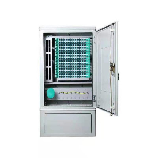
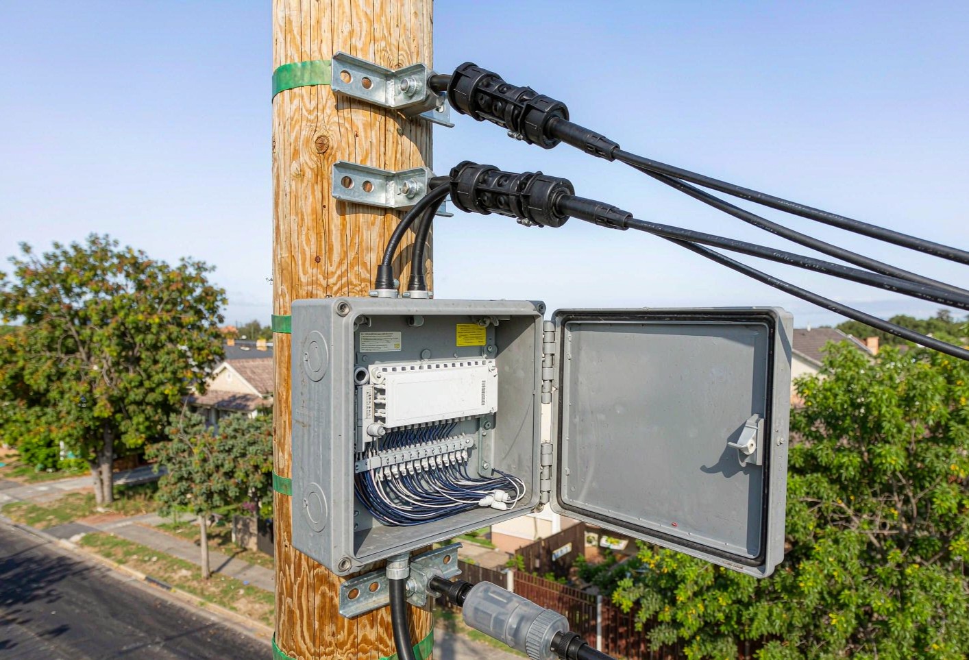
Three answers exist, all cheaper in design than on site. Dual-jacket indoor/outdoor cable uses a black PE outer jacket for the outdoor section that is stripped back at the entry point to expose a flame-retardant inner jacket carrying the rating the indoor space needs, so one cable runs from duct to rack with no mid-span splice. Terminating the outdoor cable inside the entrance facility and jointing to indoor tight-buffered cable there is the second. The third is to hand the outdoor run to an enclosure on the outside face of the wall and enter the building with indoor-rated cable from that point, the pattern most FTTH and FTTA builds use with a weatherproof fiber sonlandırma kutusu.
Whichever route is chosen, the enclosure has to be sized for the construction, not only for the fiber count. Loose tube needs tube fan-out space, a fan-out or breakout kit, room for gel handling if the cable is filled, and enough slack storage to route each 250 µm fiber without violating bend radius; a fiber optik ekleme tepsisi sized only by fiber count will be too small once the tube tails are counted. Indoor cable then lands on the frame carrying the patching, so adapter and panel density should be fixed before the cable is ordered and the optical distribution frame matched to the termination style the construction allows.
One code point belongs in the same discussion. North American rules have long allowed outside-plant cable to run indoors only for a short distance on its way to the entrance facility, historically quoted as 15 m (50 ft), and the 2026 edition of NFPA 70 reorganised the limited-energy articles, so the section number a specification cites has changed even though the intent has not. Confirm the edition the authority enforces and the distance it permits before the cable reaches the wall.
Which Field Failures Come From the Wrong Construction Choice?
Most cable complaints trace back to a construction decision made at the enquiry stage, not to a defect in the glass. Each mistake leaves a different trace on the test set, which shortens the diagnosis.
Tight-buffered cable used outdoors usually fails by water ingress and cold-temperature macrobending: attenuation climbs at 1550 nm first, the rise tracks ambient temperature, and the water penetration test on a retained sample confirms it. Loose tube pulled past its rated installation tension shows fiber strain during the pull, and the loss step appears as a discrete OTDR event where the pull snagged. Gel-filled cable brought indoors without a transition drips in the riser and slows every termination. Ribbon with poor intermittent bonding splits in the mass fusion splicer and forces single-fiber work, which is a labour problem rather than a loss problem. Rodent damage, coastal corrosion of steel armor and jacket abrasion in a rough duct each have their own visual signature, and all three are prevented at the specification stage.
The diagnostic path is short when the record is complete: compare installed attenuation against the factory test report, trace from both ends to separate a real event from a connector artifact, correlate temperature-linked behaviour with the seasonal record, and if water is suspected, cut a retained sample and run method F5B. The attenuation reference for that comparison is the same one set out in the loss budget method described by Fluke Networks (Fluke Networks, loss budget).
Cable Construction Specification Checklist
Put these twelve lines on the enquiry form and suppliers can no longer quote three different cables against the same request. Each line has a matching evidence item, and asking for the evidence before the purchase order is released is far cheaper than arguing about it at goods receipt.
| Line | What to state | Evidence to require |
|---|---|---|
| Fiber category | G.652.D, G.657.A1/A2, OM4, and the wavelength the limit applies at | Fiber datasheet with attenuation per wavelength |
| İnşaat | Central loose tube, multi loose tube stranded, tight-buffered distribution, breakout, or ribbon | Cable cross-section drawing |
| Fiber count and grouping | Total count, fibers per tube or per ribbon, ribbon count | Construction table on the datasheet |
| Water blocking | Gel-filled or dry, and the routes each applies to | Method F5B report; method E14 drip report if gel-filled |
| Taşıyıcı eleman | FRP, steel wire, aramid; dielectric or metallic | Tensile rating, installation and operational, with E1 fiber strain limit |
| Armor | Named threat: rodent, crush, tensile, induction | Armor type and thickness; E3 and E4 results |
| Jacket and fire rating | PE, PVC or LSZH; OFNP/OFNR/OFNG or Euroclass, and OFN or OFC family | Listing file number and test report, or Declaration of Performance |
| Boyutlar | Outer diameter, weight per kilometre, dynamic and static bend radius | Dimensional drawing; E11 and E6 results |
| Temperature range | Storage, installation and operating limits | Method F1 report with the temperature range used |
| Test standard | IEC 60794 parts and the acceptance line for each method | Type test report naming method, condition and result |
| Drum and marking | Length per drum, tolerance, metre marking interval, print legend content | Packing list and a photograph of the print legend |
| Documents | Factory test report, RoHS and REACH where required, origin declaration | Signed documents matching the shipped batch |
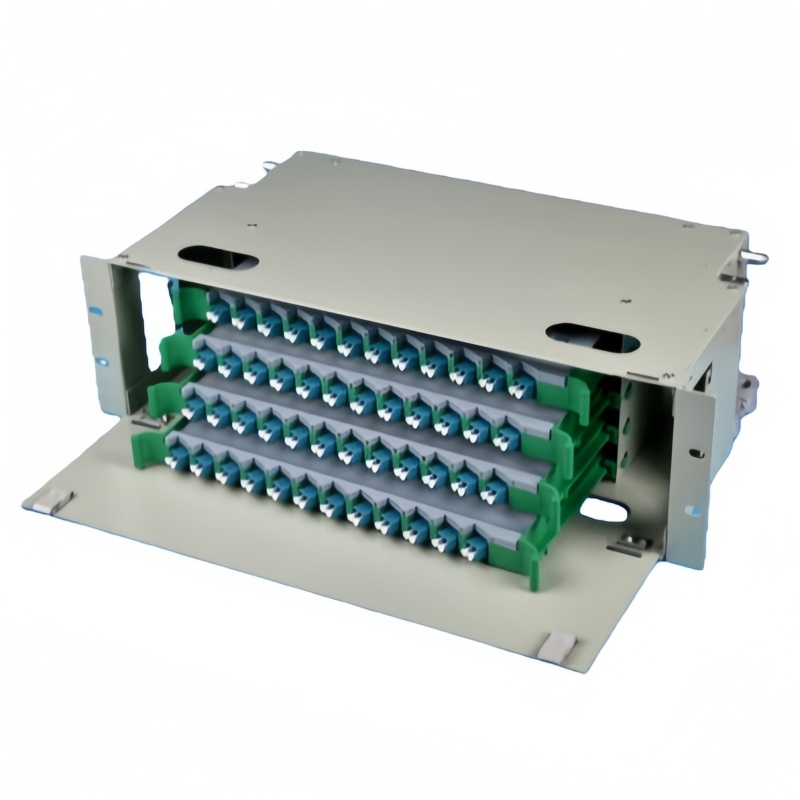
Fenxi supplies tight-buffered indoor cable, distribution and breakout builds, loose tube duct and armored outdoor cable, ribbon and high-count trunk cable, and the termination hardware that goes with them, including splice trays, termination boxes and rack frames. Send the route description, fiber count, duct dimensions, destination market and the fire class your authority requires, and our engineers will return the matching construction, the test evidence set and drum-level pricing with the quotation.