
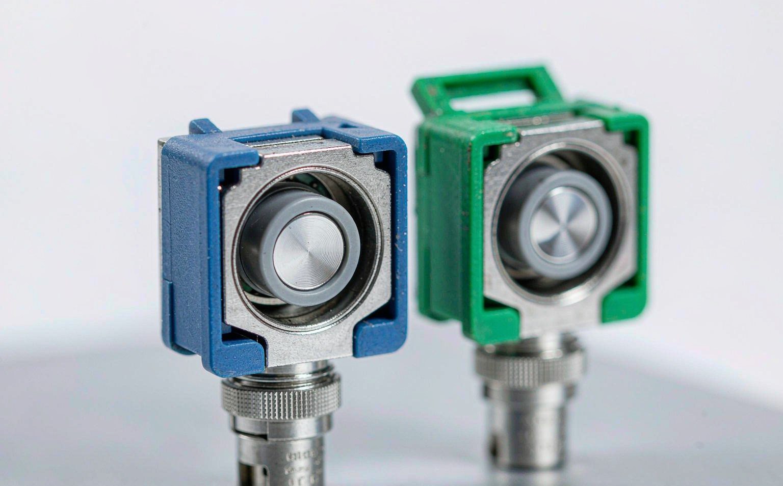
The polished end face of a fiber optic connector gets the inspection microscope, the cleaning kit and the pass/fail verdict. But the geometry that delivers that face is locked into a tiny precision cylinder or rectangle hidden inside the housing: the ferrule. Its material controls the bore accuracy, thermal expansion, wear resistance and polishability that determine whether a connection stays below 0.2 dB after repeated mating or drifts upward after the first temperature cycle.
In 2026 the passive-fiber market is expanding in two directions at once. The FTTH Council Europe reports that full-fiber networks now pass roughly 295 million homes across the EU39 group of countries, about 79 % coverage, and the organization has rebranded as Fibre Council Europe to represent data centers and 5G backhaul as well as residential access (Fibre Council Europe, 2026). At the same time, IEC is formalizing new reference ferrule interfaces: IEC 63267-3-61:2025, published in June 2026, defines cylindrical full-zirconia reference ferrules for multimode connectors, while IEC 63267-3-81:2025 covers rectangular polyphenylene sulphide (PPS) ferrules for MPO-style reference connectors, with a 16-fiber version in prEN IEC 63267-3-82:2026 under DIS ballot (IEC Webstore).
This guide is written for the engineer or buyer who has to choose between zirconia ceramic, metal and polymer ferrules for SC/LC/FC/ST and MPO/MTP assemblies. It compares real material properties, maps the standards that govern geometry and durability, and lists what must appear in an RFQ so the supplier cannot substitute a lower grade once the order is approved.

What the Ferrule Does and Why Material Is the First Decision
The ferrule is the alignment reference for the whole connector; every other performance number follows from its bore, outer diameter and surface quality. A single-mode fiber core is roughly 9 µm in diameter. Two such cores meet only because each ferrule holds its fiber on a common axis and the adapter’s split sleeve forces the two ferrules into coaxial contact. If the bore is off-center, the core is off-center, and no amount of cleaning or re-polishing removes that loss.
Cylindrical ferrules for SC, LC, FC and ST fall into two nominal outside diameters: 2.50 mm for SC/FC/ST and 1.25 mm for LC/MU. Their bore is matched to the glass cladding, commonly 125.0 µm or 125.5 µm, with a +1/−0 µm tolerance for single-mode work. Multi-mode ferrules accept 126 µm or 127 µm bores to ease ribbon fiber insertion. Outer-diameter tolerance is typically ±0.5 µm, because the adapter sleeve is a precision slip fit around that diameter. The relevant interface standards are IEC 61754-2 for SC, IEC 61754-4 for FC, IEC 61754-13 for ST and IEC 61754-7 for LC/MU (IEC Webstore).
Rectangular MT ferrules used in المنظمة البحرية متعددة الجنسيات/برنامج تخطيط وإدارة العمليات البحرية connectors hold 12, 16 or more fibers in one molded body aligned by two guide pins. Their material is usually glass-filled PPS, not zirconia, because the rectangular block must be molded with micron-level hole position and then polished as a row. Guide pins are stainless steel. The design rules are different enough that the two families should be specified separately.
Ferrule material is therefore not a cosmetic choice. It fixes the coefficient of thermal expansion (CTE), which decides how much the fiber protrudes or recesses as temperature changes. It fixes hardness, which decides how fast the bore wears during repeated mating. It fixes polishability, which decides whether an APC ferrule can hold an 8° angle within ±0.3° and a radius of curvature inside the 5–12 mm band.
How Zirconia, Metal and Polymer Ferrules Compare on Material Properties
Y-TZP zirconia dominates single-mode and APC work because it combines ceramic hardness with the highest fracture toughness among practical oxide ceramics. Yttria-stabilized tetragonal zirconia polycrystal has a Vickers hardness around 1200–1300 HV, an elastic modulus near 200 GPa and a CTE close to 10.5 × 10⁻⁶ / K at service temperatures. That CTE is higher than fused silica fiber but much lower than molded polymers, so thermal cycling does not pump the fiber out of the bore the way it can with plastic ferrules.
Alumina is even harder—about 1400–1800 HV—and more thermally stable, but it is more brittle and prone to edge chipping during polishing and handling. It appears mainly in specialty high-temperature or chemical-resistant connectors, not in mainstream telecom volumes. Stainless steel, typically 316L or precipitation-hardened 17-4PH, offers the highest impact toughness and is easy to machine or metal-injection-mold, but its CTE is roughly 16 × 10−6 / K and it is far softer than zirconia. Repeated mating can wear the bore and create particulate contamination.
Glass-filled PPS is the standard material for MT ferrules. It can be injection-molded to the rectangular shape and 0.25 mm fiber pitch that zirconia cannot economically achieve, and it absorbs less moisture than unfilled nylon or polycarbonate. The trade-off is higher CTE and lower modulus, so PPS ferrules rely on guide pins and a rigid housing for alignment and are normally rated for fewer mating cycles than cylindrical ceramic ferrules.
| المواد | Density (g/cm³) | Elastic modulus (GPa) | Vickers hardness (HV) | Fracture toughness KIC (MPa·m¹⁄²) | CTE (×10−6 / K) | Typical ferrule use |
|---|---|---|---|---|---|---|
| Y-TZP zirconia | 6.0–6.1 | 195–210 | 1200–1300 | 5–10 | 10.0–10.5 | SC/LC/FC/ST SM and APC; premium MM |
| Alumina 99 % | 3.9 | 350–380 | 1400–1800 | 3–5 | 8 | High-temp / specialty industrial |
| Stainless steel 316L | 7.8 | 193 | 150–200 | >50 | 16 | Ruggedized, sensor, vibration-prone environments |
| 17-4PH stainless steel | 7.8 | 196 | 300–400 | >50 | 11–12 | Magnetic pick-and-place / high-strength applications |
| Glass-filled PPS | 1.5–1.8 | 10–15 | <100 | low | 20–30 (flow direction) | MPO/MT rectangular ferrules |
Note: values are representative published material properties; require a supplier material certificate for any safety-critical or qualification build.
The CTE gap matters in the field. A silica fiber expands at roughly 0.5 × 10⁻⁶ / K. The epoxy bond line between fiber and ferrule has to absorb the mismatch. Zirconia’s 10.5 × 10⁻⁶ / K is already ten times higher than the glass; PPS’s 20–30 × 10−6 / K is twenty to sixty times higher. That is why MT ferrule assemblies are more sensitive to the epoxy type and curing schedule than cylindrical ceramic assemblies, and why a PPS ferrule design normally relies on a rear boot and housing to limit tensile load on the fiber row.
Why Zirconia Is the Reference for Single-Mode and APC Polish
The 8° APC cut and the sub-micron concentricity grades needed for single-mode work are both much easier to hold in zirconia than in metal or polymer. An APC ferrule must present an 8.0° ± 0.3° angle relative to its key, a radius of curvature between 5 and 12 mm, and fiber height inside the −125 to +50 nm band. Hard, fine-grained zirconia polishes to these limits repeatedly and resists the bore-edge chipping that can turn an APC ferrule into a dust source. The Fiber Optic Association connector identification reference is a useful cross-check when suppliers describe polish and housing colors differently.
Concentricity grades quoted in supplier catalogs reflect the allowed fiber-core-to-ferrule-OD offset. For single-mode work the industry uses 0.5 µm, 1.0 µm and 1.4 µm grades, with 1.4 µm often treated as the maximum acceptable for GR-326-CORE-qualified SM connectors. Tighter grades cost more because fewer ferrules survive the sorting step, but they also reduce the statistical spread of insertion loss when many cords intermate in an ODF. Multi-mode ferrules commonly allow 3–5 µm offsets because the 50 µm or 62.5 µm core tolerates larger lateral misalignment.
Bore diameter is matched to the cladding. A single-mode bore of 125.0 +1/−0 µm gives a snug fit that centers the core without cracking the glass during assembly. A 125.5 µm or 126 µm bore is used when the fiber has a thicker coating or when epoxy viscosity requires more clearance. The wrong bore is a latent defect: the connector may pass an initial loss test, then drift when vibration or temperature moves the fiber inside a loose bore.
Durability also favors zirconia in high-cycle applications. Cylindrical ceramic ferrules regularly qualify to 500 mating cycles with less than 0.2 dB insertion-loss change under Telcordia GR-326-CORE, and many vendor data sheets still quote that level. IEC 61753-1:2018/AMD1:2020 reduced the routine test severity for cylindrical connectors to 200 cycles in indoor categories, reflecting field data that most connectors are mated far less often, but the zirconia material itself is capable of the higher figure when required.
When Metal Ferrules Fit and What They Give Up
Stainless steel ferrules are the right choice when the connector must survive impact, vibration or corrosive exposure rather than deliver the lowest possible insertion loss. 316L offers excellent salt-spray resistance and absorbs mechanical shock without chipping. 17-4PH can be heat-treated to higher hardness and is ferromagnetic in the H900 condition, which is useful for automated pick-and-place assembly of small-form connectors.
The optical penalty is real. Steel is softer than zirconia, so the bore can enlarge and the surface can gall during repeated mating. The result is a higher typical insertion loss, commonly 0.2–0.3 dB, and faster degradation if the connector is mated and unmated frequently. For that reason, metal ferrules are rarely used for single-mode APC; the angled geometry and reflectance budget need the surface stability of ceramic.
Common metal-ferrule applications include industrial sensors, military tactical reels, oil and gas instrumentation, and field-deployable patch cords where the connector housing itself is part of the strain-relief system. In these cases the procurement document should call out the steel grade, passivation and any magnetic property requirement, because a 316L ferrule that has been replaced by a 17-4PH ferrule without notice can change the insertion-loss distribution and the assembly automation behavior at the same time.
MPO and MT Ferrules Use a Different Material Stack
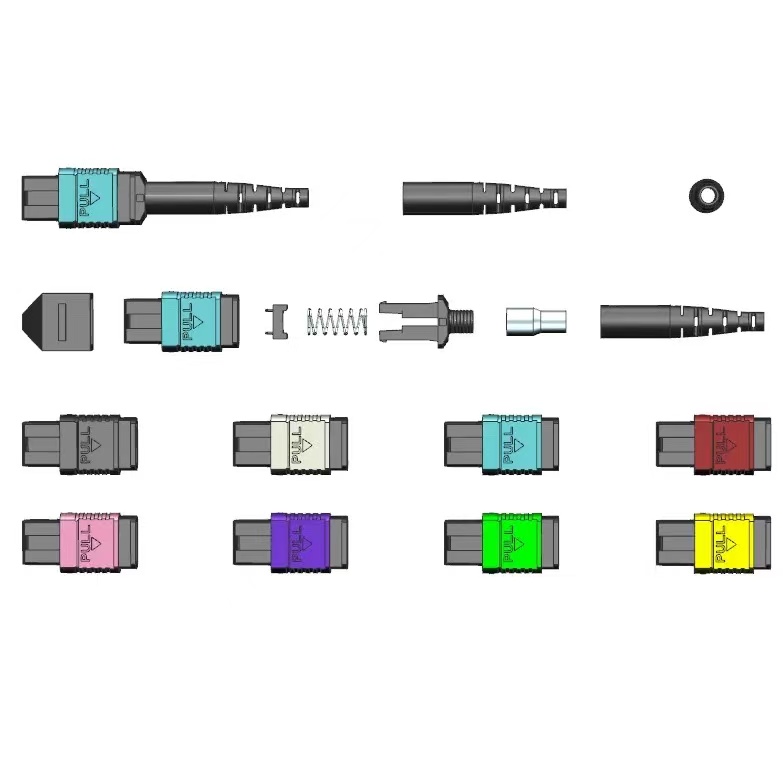
Do not specify an MPO ferrule as if it were a large zirconia cylinder; it is a molded PPS rectangle with precision steel guide pins. The IEC 61754-7 and TIA-604-5 (FOCIS 5) interface defines a 6.4 mm face width, 2.5 mm height and a 2.75 mm centre-to-centre guide-pin spacing. Fiber holes are spaced at 0.25 mm, and the most common 12-fiber ferrule is roughly 8.0 mm wide in the body. The same form factor scales to 16, 24, 32 and more fibers. TIA publishes the physical interface details through TIA-604-5.
The PPS body has two consequences for procurement. First, the rectangular ferrule cannot be re-polished as easily as a cylindrical ferrule; the whole row has to be lapped together, and coplanarity of every fiber matters. Second, durability is lower. FSG Networks quotes GR-1435-CORE mating cycles at 50 or more for MT ferrules, compared with 200–500 for cylindrical ferrules. That difference is inherent to the material and the larger contact area, not a quality failure.
Fiber hole and eccentricity grades for MT ferrules are usually labeled MM (multi-mode standard), ML (multi-mode low-loss), SM (single-mode) and SMLL (single-mode low-loss). The hole diameters and eccentricity tighten as loss class improves. For example, a typical 12-fiber single-mode low-loss ferrule uses a 125.2 +0.5/−0 µm fiber hole, 699 +0.5/−0 µm guide-pin hole and 0.7 µm maximum eccentricity, while a multi-mode standard ferrule uses 126 +2/−0 µm and 2.5 µm eccentricity. ULL MPO assemblies can hold below 0.25 dB per channel maximum and below 0.15 dB typical after repeated mating.
| MT ferrule grade | Fiber hole (µm) | Pin hole (µm) | Max eccentricity (µm) | Typical max IL (dB) | Typical IL (dB) |
|---|---|---|---|---|---|
| MM standard | 126 +2/−0 | 700 +1/−1 | 2.5 | 0.50 | 0.20 |
| ML multi-mode low-loss | 126 +1/−0 | 700 +1/−1 | 1.4 | 0.35 | 0.20 |
| SM single-mode | 125.2 +1/−0 | 700 +0/−1 | 1.4 | 0.50 | 0.20 |
| SMLL single-mode ultra-low-loss | 125.2 +0.5/−0 | 699 +0.5/−0 | 0.7 | 0.35 | 0.15 |
Source: industry supplier MT ferrule specification tables and Fujikura ULL MPO product data.
The 2026 standards activity reflects the density shift. IEC 63267-3-81:2025 codifies the rectangular PPS ferrule for 12, 8, 4 and 2 multi-mode reference connectors, while prEN IEC 63267-3-82:2026 carries a 16-fiber PPS rectangular ferrule through DIS ballot. Those documents do not change the material choice, but they give buyers a published reference for the geometry that a high-count MPO ferrule must deliver. US Conec publishes handling guidance for the MTP platform that applies to any high-density MPO build.
The Adapter Sleeve Is Part of the Ferrule Decision
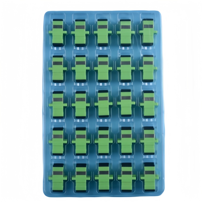
A ferrule does not mate with another ferrule; both sit inside a split sleeve that becomes the common axis. Sleeve material therefore belongs in the same specification. Ceramic split sleeves, usually zirconia, give the tightest bore and the longest wear life. They are the normal choice for single-mode and APC adapters because they match the ferrule hardness and do not deform under the higher retention force needed for low-reflectance contact. Phosphor bronze sleeves are common in multi-mode adapters; they are cheaper and forgiving of larger core offsets, but they wear faster and can gall.
TIA-568.3-D and IEC 61753-1 treat the adapter as a separate passive component, but the same durability logic applies. A ceramic-sleeved SC or LC adapter is normally expected to survive 500 mating cycles with little change in retention force. When the sleeve wears, the ferrule pair starts to sit eccentrically, and insertion loss becomes sensitive to which way the connector is twisted during insertion. Field troubleshooting should always include a known-good adapter and a known-good reference cord before blaming a cable lot.
For high-density panels, the sleeve choice also affects the insertion force. A tight ceramic sleeve keeps loss low but makes patching stiffer. A bronze sleeve is easier to mate in dense LC panels but may not hold the same geometry under vibration. Our محول الألياف البصرية range lists ceramic and bronze sleeve options so the sleeve can be matched to the ferrule material and the application.
What Testing Proves the Ferrule Grade?
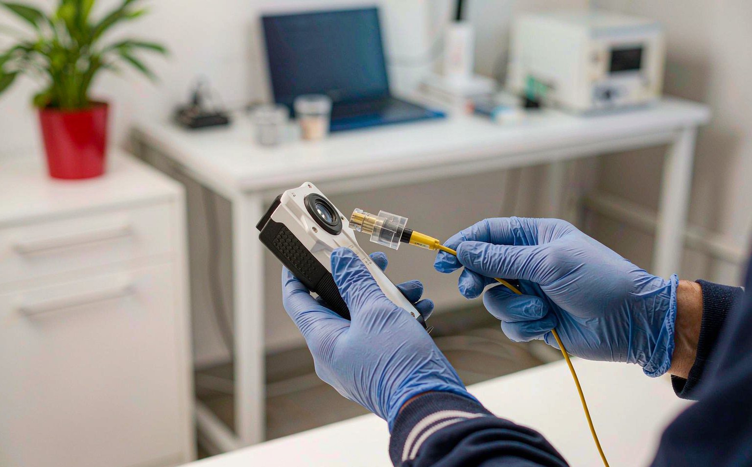
A material name on a data sheet proves nothing without geometry and durability evidence. The relevant test hierarchy is: end-face geometry per IEC 61755-3-1 (PC/UPC single-mode), IEC 61755-3-2 (APC single-mode), IEC 61755-3-31 (MPO minus-side geometry) and IEC 61755-6-2 (or the new IEC 63267 series for reference connectors); insertion loss and return loss per IEC 61300-3-4 and IEC 61300-3-6; visual inspection per IEC 61300-3-35; and environmental/mechanical durability per IEC 61300-2-2 (mating), IEC 61300-2-4 (fiber retention), IEC 61300-2-22 (thermal cycling), IEC 61300-2-17/2-18 (low/dry heat) and salt mist where needed.
The pass/fail bands must match the polish type. For single-mode UPC/PC the end-face geometry band is radius 7–25 mm, apex offset ≤50 µm and fiber height −125 to +50 nm. For APC the radius band tightens to 5–12 mm, apex offset stays ≤50 µm, and the angle must be 8.0° ± 0.3° relative to the key. These numbers are reviewed in the Fenxi دليل هندسة السطح الأمامي للموصل; the point here is that they are ferrule-level outputs, not cable-level outputs. The Fluke Networks fiber-inspection guidance covers the visual half of the same discipline.
| Test item | Reference standard | What the report must show | Typical acceptance |
|---|---|---|---|
| هندسة الوجه النهائي | IEC 61755-3-1 / -3-2 / -3-31; IEC 63267 series for reference grade | Radius, apex offset, fiber height, angle/key error, concentricity / coplanarity | UPC/PC: ROC 7–25 mm, apex ≤50 µm, height −125 to +50 nm; APC: ROC 5–12 mm, angle 8.0° ± 0.3° |
| فقدان الإدراج | IEC 61300-3-4 | Per-connector or per-channel IL at 1310/1550 nm (SM) or 850/1300 nm (MM) | ≤0.25 dB for standard SM; ≤0.35 dB for standard MPO; lower for ULL |
| خسارة الإرجاع | IEC 61300-3-6 | Per-connector RL at test wavelength | ≥50 dB UPC, ≥60 dB APC, ≥30 dB MM |
| متانة التزاوج | IEC 61300-2-2 or GR-326-CORE / GR-1435-CORE | IL change after defined cycles | Cylindrical: ΔIL ≤0.2 dB at 200–500 cycles; MT: ≥50 cycles |
| Environmental cycling | IEC 61300-2-22 thermal; IEC 61753-1 category | IL/RL before, during and after cycle sequence | Category C: −10°C to +60°C; OP: −25°C to +70°C; I: −40°C to +70°C with vibration/salt options |
| End-face visual | IEC 61300-3-35 | 400× inspection image of core zone | No defects in 50 µm core zone before shipment |
Category selection follows IEC 61753-1:2018/AMD1:2020. C covers controlled indoor environments such as data centers and central offices. OP adds humidity and salt-mist requirements for protected outdoor cabinets. OP+ and I add industrial stressors, while E covers extreme temperature ranges. Specifying the category on the purchase order prevents a supplier from testing indoor-grade ferrule bonds against an outdoor temperature range that the epoxy was never meant to survive.
Common Ferrule Failure Modes and How to Trace Them
Most ferrule failures look like dirty or high-loss connectors until the root cause is under a microscope. Use the following diagnostic order so the field team does not clean, replace and curse good cables while the real problem stays in the adapter or ferrule.
- Chipped or cracked ferrule tip. Common after an APC connector is mated to a UPC adapter, after a connector is dropped, or after over-tightening an FC threaded coupling. Inspect at 400× before cleaning; a chip in the 50 µm core zone is a reject.
- Bore wear and enlarged hole. Cumulative mating wears the bore, especially in metal or low-grade polymer ferrules. The symptom is an insertion loss that worsens with vibration or temperature, because the fiber has room to move.
- Alignment sleeve wear or contamination. A worn bronze sleeve can make every connector plugged into that adapter test high. Swap in a known-good adapter before condemning a cable lot.
- Fiber pistoning / epoxy wicking. CTE mismatch, under-cured epoxy or moisture absorption can push the fiber above or below the ferrule surface. The symptom is good loss with a clean end face but intermittent reflectance spikes; interferometry shows fiber height outside band.
- Guide-pin damage in MPO/MT. Bent or loose pins shift the whole row. One channel may pass while its neighbor fails, or the whole connector tests high after one rough insertion.
- MT ferrule row coplanarity loss. One fiber in a twelve-fiber row sits low or high. Eleven channels pass; one does not. The fix is per-ferrule geometry screening, not more cleaning.
- APC angle or key error. A perfectly polished 8° ferrule mated to an adapter whose key is rotated behaves like a bad angle. Always check angle relative to key and sleeve key orientation.
When a lot shows mixed pass/fail results, isolate a failed sample and inspect its geometry with a 3D interferometer. If the geometry is good, move to adapter and cable routing. If the geometry is bad, return the lot and demand a material and process certificate for that production batch.
Ferrule Material RFQ Data Sheet
A complete RFQ turns the ferrule from a hidden assumption into a controlled item. Send the table below to the supplier and ask for evidence tied to the production lot. Without these fields, the lowest bidder can change the ferrule grade or sleeve material mid-contract.
| RFQ field | What the buyer must state | What the supplier must return |
|---|---|---|
| Connector / ferrule family | SC/LC/FC/ST or MPO-12/16/24; polish type | Interface drawing and IEC 61754 part reference |
| Ferrule material and grade | Y-TZP zirconia, 316L, 17-4PH, PPS, etc.; bore tolerance class | Material certificate and bore / eccentricity distribution |
| Cylindrical geometry | OD tolerance ±0.5 µm; SM concentricity ≤1.0 or 1.4 µm; MM concentricity class | Per-lot concentricity report or certificate |
| MT geometry | MM/ML/SM/SMLL grade; fiber hole and pin hole tolerance; eccentricity | Per-ferrule geometry sheet and coplanarity data |
| End-face specification | UPC/PC or APC; ROC, apex offset, fiber height, angle tolerance | تقرير جهاز التداخل لكل دفعة إنتاج |
| Adapter sleeve | Ceramic zirconia or phosphor bronze; retention force if specified | Sleeve material evidence and adapter durability data |
| Durability and environment | Target mating cycles; IEC 61753-1 category (C, OP, OP+, I, E) | Test summary per IEC 61300-2-2 and environmental cycle data |
| الأداء البصري | IL/RL limits per channel; test wavelength | Factory test report tied to serial or lot number |
| Identification and packaging | Lot traceability, dust caps, individual bags, port sequencing | Label proof and packing list before production |
| Schedule and first article | First-article quantity, drawing approval gate, production lead time | Sample report, approval date, split-shipment plan, warranty |
Require a first article for every new ferrule material or supplier. Inspect it for the same geometry, material and sleeve combination that the production lot will use. A supplier who ships a first article with premium zirconia and then switches to a lower grade cannot be caught by final optical testing alone; only the material certificate and geometry report expose the change.
Fenxi builds SC, LC, FC, ST and MPO/MTP patch cords, pigtails and adapters with zirconia, metal or PPS ferrules selected for the target environment. Send the application, the required IEC 61753-1 category and any geometry limits, and our engineers will confirm the ferrule material, sleeve type and test plan before quoting.