
Two patch cords that look identical in a product photo will not mate usefully if one carries an angled ferrule and the other a domed one. Polish geometry decides how much light reflects back toward the transmitter, and it is fixed at the factory, so a polish mismatch that reaches site is not corrected with a cleaner or a torque wrench — it is corrected by re-ordering. The buyers who get caught specify polish by housing colour alone, or inherit a bill of materials without checking what the optics expect.
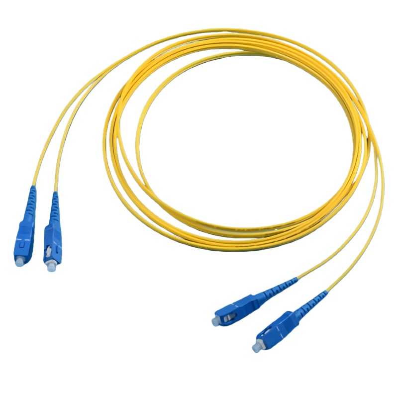
How PC, UPC and APC Change the Reflection
All three polish types solve one problem: when two fiber end faces meet inside an adapter, any air gap at the interface bounces light straight back down the core. That returning energy is measured as return loss, and each polish family attacks the gap differently.
PC, physical contact, replaced the original flat-polished ferrule with a shallow dome so that the two cores press together at the centre. UPC applies a longer polish cycle to the same domed shape, producing a finer surface and a smaller radius of curvature that concentrates contact pressure directly over the core. APC takes a different route: the ferrule face is polished at 8 degrees, so reflected light leaves the core and exits into the cladding instead of travelling back to the laser. The angle is what produces the return-loss advantage, not the surface finish. Both UPC and APC deliver low insertion loss, and the difference between them there is small enough that return loss, not insertion loss, is the deciding number.
| Polished interface | Geometría de la cara frontal | Pérdida de retorno típica | Pérdida de inserción típica | Housing colour | Donde debe estar |
|---|---|---|---|---|---|
| PC (contacto físico) | Domed ferrule, large radius of curvature | −35 to −40 dB | ≤0,3 dB | Blue or beige | Legacy multimode and first-generation telecom ports |
| UPC (contacto físico extremo) | Domed ferrule, tight radius, finer finish | ≤−50 dB | ≤0.25 dB | Azul | Data centre and metro patching, transceiver links, general single-mode |
| APC (contacto físico en ángulo) | 8° angled face with a polished dome | ≤−60 dB | ≤0,3 dB | Green (keyed) | PON and FTTH, CATV, RF-over-fiber, DWDM nodes |
Return Loss Is a Logarithmic Score, Not a Percentage
The gap between −40 dB and −60 dB looks modest in a table and is enormous in practice, because decibels are logarithmic: 20 dB is a hundredfold reduction in reflected power, from roughly 0.01 % down to 0.0001 %. On a short digital link that difference is invisible. On a passive optical network it is the difference between a stable link and intermittent errors, because an unmated port behaves as a mirror. During a phased FTTH rollout, subscriber ports on a PLC splitter sit dark for months; with UPC interfaces each one reflects power back toward the OLT, and the cumulative return can disturb subscribers already sharing that branch. An angled interface deflects that light whether or not a mating connector is present, which is why GPON and its successors specify angled interfaces throughout the optical distribution network in the Serie G.984 de la UIT-T.
Reflection also interacts with the laser itself: back-reflected light re-enters the source cavity, shifts the emitted wavelength and raises relative intensity noise, which is harmless in a tolerant digital receiver and damaging in an analog channel. The split-ratio and reach consequences are worked through in our PON power budget guide.
Where Reflectance Actually Costs Money
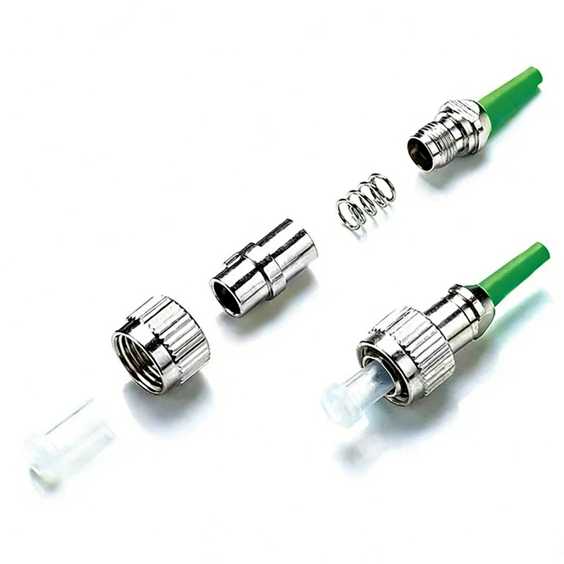
Analog transport is the most demanding case. CATV and RF-over-fiber carriers modulate the light directly, so reflection shows up immediately as carrier-to-noise degradation rather than as a slowly rising error rate. Dense wavelength-division systems care for a different reason: a reflective interface acts as a weak cavity that can pull a laser off its assigned wavelength. Long-haul spans accumulate reflections from every connector, so a few UPC joints inside an otherwise angled plant can eat the loss margin the design assumed.
Data centre links are the mirror image of that argument. Transceiver cages, cassettes and patch panels in a 100G or 400G build are engineered around UPC end faces, where insertion loss is the priority and green hardware creates a compatibility problem rather than an optical benefit. TIA-568.3-D keeps the structured-cabling side of that decision separate from the carrier side, and the connector identification charts published by the Asociación de Fibra Óptica are a quick way to classify a mixed panel before anyone orders parts.
Reading Polish Type in the Field, and the Rule You Cannot Break
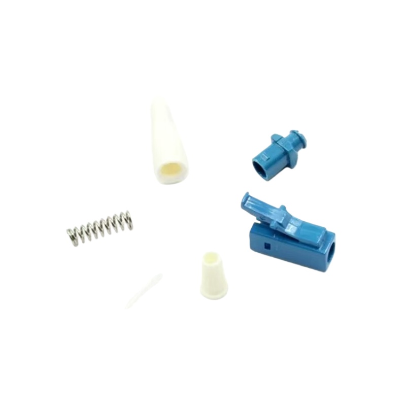
Colour is a useful first clue and a poor final answer. Blue normally means UPC and green means APC across the SC, LC and FC families, but colour codes polish only: it says nothing about single-mode versus multimode, and legacy blue housings can carry a PC ferrule. The boot marking or part number is the authoritative record, and a 200x scope settles it in seconds: an angled face is visibly slanted in profile and the core sits off centre.
The one rule with no exceptions is that APC and UPC must never be mated. The 8-degree face against a flat dome leaves a wedge-shaped air gap: insertion loss rises sharply, return loss collapses toward a bare-air reflection, and the concentrated contact pressure can scratch or crack a ferrule permanently. Keyed green adapters make the mistake hard indoors, but they do not help at a transceiver cage or test port where keying is absent. Where a UPC plant must meet an APC port, the conversion belongs in a purpose-built hybrid assembly at a defined boundary, not a forced mating at the panel. Our adapter range includes the keyed green and blue bulkheads that enforce this at the rack face.
Matching Polish to Each Segment of the Build
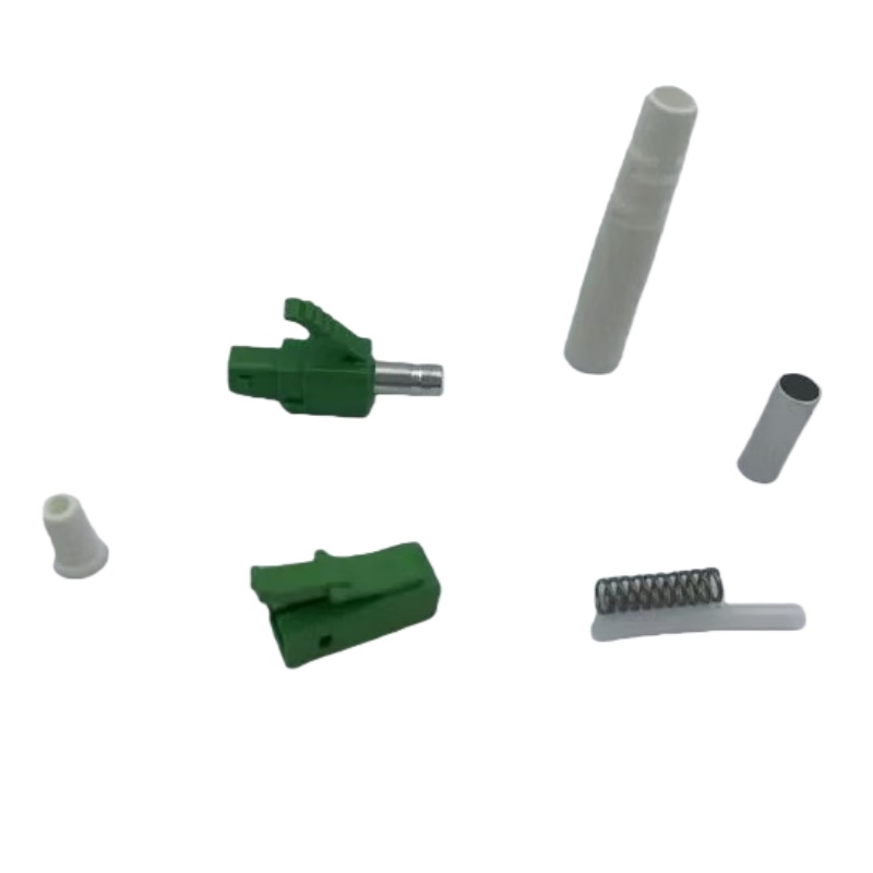
Polish is a per-segment decision, not a site-wide rule, and the cleanest projects write it into the cable schedule so the pull crews never guess.
| Network segment | Polaco | Why it is specified that way | What goes wrong when it is not |
|---|---|---|---|
| FTTH ODN, splitter to ONT | APC throughout | Dark splitter ports reflect; the PON ODN is designed around angled interfaces | A blue cord on a green port creates a wedge gap and a repeat fault call |
| Metro and backbone DWDM nodes | APC at reflective nodes | Kills the weak cavity that shifts laser wavelength | Per-shelf polish drift between two vendors |
| CATV and RF-over-fiber | APC | Analog carriers degrade immediately with reflection | Carrier-to-noise complaints that look like a transmitter fault |
| Data centre 100G / 400G transceiver links | UPC unless the module states otherwise | Modules and cassettes are built around domed interfaces; insertion loss dominates | Green hardware mated into a UPC-only port |
| Legacy multimode LAN | PC or UPC, replaced rather than re-polished | Installed base and adapters are flat or domed | Live plant disturbed for a polish change nobody needs |
| ODF bulkheads and field-installable connectors | Same polish as the branch it serves | The adapter key and the ferrule have to agree | Correct green adapter, incorrect blue connector |
Fenxi builds both polish families on the same lines, so a mixed programme can be supplied as cables de conexión monomodo with polish, keying and colour already matched to each segment.
What to Put on the Purchase Order
Two vendors can both ship a green angled connector and deliver different geometry, so the specification has to name the parameters that actually control the optical result: radius of curvature, apex offset, fiber height or undercut, and the key width that sets rotational alignment against the adapter. IEC 61755-3 covers the optical interfaces for these ferrules, and a supplier should be able to quote against it.
Three further lines belong in the order. First, insertion loss and return loss limits per mated pair with a stated test wavelength, and a decision on whether testing is 100 % or by sample — on an angled product the return-loss test is the one that catches a bad polish angle. Second, mating durability, typically 500 matings under GR-326-CORE style qualification, which matters on test ports that are re-patched constantly. Third, end faces delivered clean and capped, with the inspection method agreed in advance; the reference sequence is the método de inspección de fibras published by Fluke Networks, and TIA intermateability standards settle disputes about whether parts from different lots should mate.
Total Cost of Ownership: Where the Money Actually Goes
A green connector costs a little more than a blue one, and that difference is rarely the deciding number. The expensive line is field rework: a polish mismatch found at acceptance testing costs a truck roll, a re-termination and a retest for every affected port, and the labour dwarfs the component premium. The second line is stocking complexity, since a mixed plant needs both keyed adapter families on the van.
| Cost line | UPC-only plant | APC plant (PON, CATV, DWDM) | Five-year effect |
|---|---|---|---|
| Unit cost per assembly | Referencia | Small premium from the angle polish step | A few percent of connector spend only |
| Reflection-related fault calls | Higher wherever ports sit unmated or analog carriers run | Low, because angled faces deflect return light | Largest controllable operating line |
| Field rework from mixed polish | Occurs when a blue cord reaches a green port | Avoided by one written rule in the schedule | Dominated by labour and retest, not parts |
| Spares and adapter stock | One keyed family | Two keyed families where the plant is genuinely mixed | Small, and reduced by segmenting the schedule |
| Acceptance test time | Fast on tolerant digital links | Slightly longer where return loss is measured per port | Paid back the first time a fault is caught at handover |
The conclusion for most buyers is not to pick one polish for the whole estate but to fix the polish per segment and then hold the supply chain to it. Fenxi supplies both families from the same factory: Conectores SC y Conectores LC in UPC and APC versions, matching adapters, pigtails and patch cords, with insertion loss and return loss recorded per assembly. Send your cable schedule, connector families and target return-loss limits, and our engineers will quote a polish-matched package against the standard your project is specified to.