
A data center’s cabling plant is the part of the building that outlives every server generation. The switches and transceivers change every three to five years; the fiber between MDA, HDA and EDA is expected to last fifteen to twenty-five. That is why TIA-942 organizes the room into zones before a single cable is pulled, and why a zone drawn in the wrong place becomes an expensive recabling project the first time bandwidth doubles.
ANSI/TIA-942-C, the 2024 revision of the Telecommunications Infrastructure Standard for Data Centers, formalizes the hierarchy and adds single-pair Ethernet, updated cabinet sizing and explicit guidance for high-density AI racks (TIA, 2024). TIA’s TR-42.1 committee has also begun work on Addendum 1: Artificial Intelligence to ANSI/TIA-942-C, with publication targeted for mid-2027 to address dense GPU clusters, liquid cooling and high-speed fiber (Telecommunications Industry Association, 2026). Meanwhile TIA’s data center certification program has passed 1,000 certification activities across more than 800 data centers in over 60 countries (TIA, 2026 Q&A). The message is clear: infrastructure is now audited like a production system.
This guide maps the functional zones, the cabling distances between them, the loss budgets that decide whether 400G/800G links pass certification, and the cabinet and pathway sizing that keeps dense fiber manageable. It is written for the engineer or procurement lead who has to specify the passive layer before the active equipment ships.
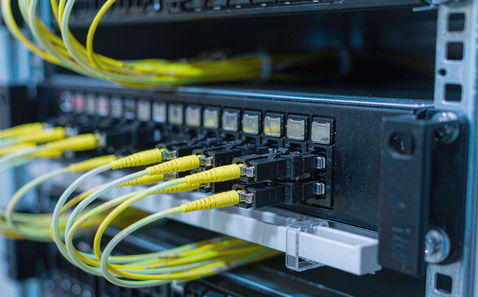
What Are the TIA-942 Cabling Zones?
TIA-942-C splits the data center into functional areas. Each area has one job: bring traffic in, aggregate it, distribute it horizontally, or terminate it at the equipment.
- Entrance Room (ER). The demarcation point where carrier circuits meet the building cabling. ER may be inside or outside the computer room. For security, many operators locate it outside the white space so provider technicians never enter the secure hall.
- Main Distribution Area (MDA). The central hub. It houses the main cross-connect and the core routers, LAN switches and SAN switches. All backbone cabling terminates here: ER-to-MDA, MDA-to-HDA, and MDA-to-IDA where present.
- Intermediate Distribution Area (IDA). Optional. Used in large multi-floor or multi-hall facilities where a single MDA would create unmanageable fiber counts. It is an aggregation tier between MDA and HDA.
- Horizontal Distribution Area (HDA). The transition between backbone and horizontal cabling. Each HDA typically serves a row or a zone, hosting aggregation switches and the horizontal cross-connect.
- Zone Distribution Area (ZDA). Optional consolidation point inside the horizontal run. It must not contain cross-connects or active equipment. It is useful in modular halls where pre-terminated trunks land at a central point and shorter patch cords fan out to racks.
- Equipment Distribution Area (EDA). The server and storage racks themselves. This is where horizontal cabling terminates at patch panels or directly at equipment ports.
| Zona | Primary function | Typical location | Active equipment? | Dominant cable type |
|---|---|---|---|---|
| ER | Carrier demarcation and entrance | Building perimeter, adjacent to MDA | Carrier/ISP gear | OS2 single-mode backbone |
| MDA | Core cross-connect and aggregation | Center of data hall or meet-me-room | Core routers/switches | OS2 backbone + breakout to HDA |
| IDA | Optional intermediate aggregation | Between MDA and remote halls | Aggregation switches | OS2 backbone |
| HDA | Row-level horizontal cross-connect | End or middle of each row | Aggregation/access switches | OM4/OM5 to EDA; OS2 to MDA |
| ZDA | Optional consolidation point | Mid-row or modular zone | Nenhum | Pre-terminated trunk + short patch cords |
| EDA | Server/storage termination | Individual racks | Servers, storage, ToR switches | Cat6A/DAC for management; OM4/OS2 fiber uplinks |
The signal flow is hierarchical: ER → MDA → (IDA →) HDA → (ZDA →) EDA. Deviating from this star topology to save cable usually creates dark fiber, undocumented cross-connects and moves that require a physical construction project instead of a patch-cord change.
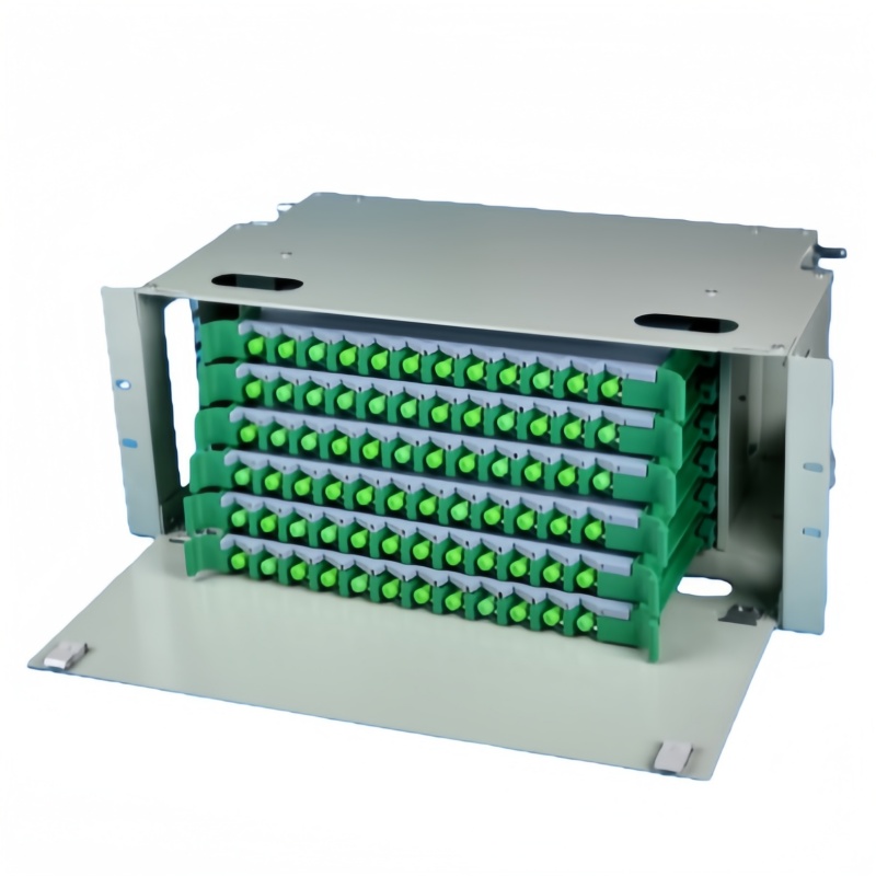
Which Topology Fits Your Data Center?
The zone plan depends on how servers connect to the network. Three topologies dominate, and the choice changes the HDA count, the horizontal cable volume and the switch count.
Top-of-Rack (ToR). A small access switch sits at the top of every server rack. Servers connect with 1–3 m copper or fiber patch cords. The ToR switch uplinks to the row aggregation switch in the HDA, usually over 40G/100G/400G fiber. ToR minimizes long horizontal runs and makes server moves easy, but it adds switch count and license cost. It is the default in hyperscale and high-density AI clusters.
End-of-Row (EoR). One or two aggregation switches sit at the end of the row; every server in the row runs a horizontal cable to the EoR switch. EoR reduces switch count, but it multiplies horizontal cable length and makes rack additions disruptive. It works best in moderate-density rows with stable populations.
Middle-of-Row (MoR). The aggregation switch is centered in the row, halving the maximum horizontal run compared with EoR. It is a compromise for long rows where ToR cost is rejected but EoR distance limits are exceeded.
| Topologia | Avg horizontal run | Switch count | Fiber/copper per rack | Melhor ajuste |
|---|---|---|---|---|
| Top-of-Rack (ToR) | 1–3 m intra-rack | One per rack | Low horizontal; high uplink fiber to HDA | Hyperscale, AI clusters, fast moves |
| End-of-Row (EoR) | 5–30 m per server | 1–2 per row | High horizontal; low switch count | Stable moderate-density rows |
| Middle-of-Row (MoR) | 3–15 m per server | 1–2 per row | Moderate horizontal; mid switch count | Long rows, cost-sensitive stable loads |
In ToR designs the HDA still matters: it is where the row aggregation switch uplinks to the MDA. In very small halls the MDA and HDA may be combined, which simplifies zoning but removes the physical separation that makes future scaling easier.
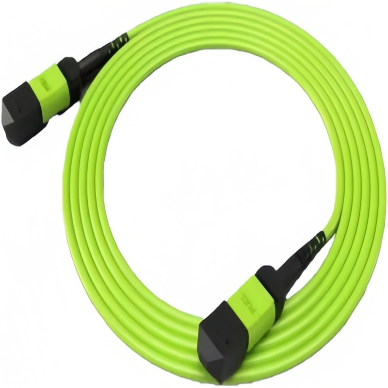
How Far Can Each Fiber Grade Run?
TIA-942-C does not invent distance limits; it points to the active equipment’s transceiver specification and the channel loss budget calculated per TIA-568.3-D. The practical reach table below is built from IEEE 802.3 Ethernet physical-layer clauses.
| Ethernet application | Padrão | OM3 reach | OM4 reach | OM5 reach | OS2 reach | Conector |
|---|---|---|---|---|---|---|
| 10GBASE-SR | IEEE 802.3ae Clause 52 | 300 m | 400 m | 400 m | Not specified | LC duplex |
| 40GBASE-SR4 | IEEE 802.3bm Clause 86 | 100 m | 150 m | 150 m | Not specified | MPO-12 |
| 100GBASE-SR4 | IEEE 802.3bm Clause 86 | 70 m | 100 m | 100 m | Not specified | MPO-12 |
| 200GBASE-SR4 / 100GBASE-SR2 | IEEE 802.3cd Clause 138 | 70 m | 100 m | 150 m | Not specified | MPO-12 |
| 400GBASE-SR8 / 400GBASE-SR4.2 | IEEE 802.3cm Clause 138 | 70 m | 100 m | 150 m | Not specified | MPO-16 / LC duplex |
| 800GBASE-SR8 | IEEE 802.3df Clause 185 | 60 m | 100 m | 100 m | Not specified | MPO-16 |
| 400GBASE-DR4-2 | IEEE 802.3df | Not applicable | Not applicable | Not applicable | 2 km | MPO-12 |
| 800GBASE-DR8 | IEEE 802.3df | Not applicable | Not applicable | Not applicable | 500 m | MPO-16 |
| 800GBASE-DR8-2 | IEEE 802.3df | Not applicable | Not applicable | Not applicable | 2 km | MPO-16 |
Two trends are visible. First, multimode reach compresses as lane rates rise: OM4 holds 100 m from 100G through 800G, but OM3 drops from 300 m at 10G to 60 m at 800G. Second, 800G forces MPO-16 or higher fiber counts; MPO-12 trunks that carry 100G/400G SR4 do not have enough fibers for 800G SR8 without lane splitting or new hardware. OS2 single-mode is the safe choice for any backbone whose final length or speed is not yet known.

The Loss Budget Problem at 400G and 800G
At 10G a channel could absorb several decibels of unplanned loss and still pass. At 800G the budget is measured in tenths of a decibel, and the first place it is lost is usually a dusty connector or a tight bend behind the patch panel.
TIA-568.3-D caps a mated single-fiber connector pair at 0.75 dB. Pre-terminated MPO assemblies are typically specified tighter, at 0.35 dB or better per mated pair, with low-loss variants down to 0.20 dB. A fusion splice is normally budgeted at 0.3 dB or less, though 800G SR4.2 demands below 0.1 dB per splice if splices are used at all.
The channel budgets from IEEE 802.3 are the real constraints. 100GBASE-SR4 allows up to 1.9 dB, 400GBASE-SR8 up to 1.9 dB on OM4, and 800GBASE-SR8 narrows to 1.8 dB (Fluke Networks, 2026). For an 800G SR8 link with two MPO-16 patch-panel connections at 0.35 dB each, only 1.1 dB remains for the trunk and any margin. A single 5 µm particle on an MPO end face can add 0.5–1.0 dB, which is why end-face inspection to IEC 61300-3-35 is now a commissioning requirement, not a best practice.
Single-mode short-reach links add a reflectance problem. 800GBASE-DR8 and DR8-2 allow only two discrete connector reflectance values of -31 dB, or eight of -40 dB, which makes APC polish and OTDR-based Tier 2 testing the safe specification for those links (Fluke Networks, 2026).
| Aplicativo | Channel IL max | Typical MPO pair loss | Remaining for fiber | Critical failure mode |
|---|---|---|---|---|
| 100GBASE-SR4 OM4 100 m | 1.9 dB | 2 × 0.35 dB | 1.2 dB | Dirty MPO ferrule |
| 400GBASE-SR8 OM4 100 m | 1.9 dB | 2 × 0.35 dB | 1.2 dB | Bend radius violation behind panel |
| 800GBASE-SR8 OM4 100 m | 1.8 dB | 2 × 0.35 dB | 1.1 dB | Contamination + marginal splices |
| 800GBASE-SR4.2 OM4 100 m | 1,0 dB | 2 × 0.25 dB | 0,5 dB | Any field splice or high-loss bend |
The lesson for procurement: specify factory-tested, pre-terminated trunks with guaranteed insertion-loss values, and write end-face inspection into the acceptance plan. Field terminations and uninspected connectors are the fastest way to turn a paper-compliant design into a failed certification.
How Should a TIA-942 Cabling System Be Tested and Accepted?
Testing is not a single check; it is a sequence that matches the way failures propagate. Start with continuity and loss, then characterize events, then inspect end faces, then verify labels and polarity.
Tier 1 testing uses an optical loss test set (OLTS): a stabilized light source and power meter at each end of the link. The result is the total insertion loss of the channel, compared against the application budget. Every backbone and horizontal fiber link should be Tier 1 tested after installation and before the first active equipment is patched in. For multimode, test at 850 nm and 1300 nm; for single-mode, test at 1310 nm and 1550 nm. Record the result against the link identifier in the DCIM or AIM system.
Tier 2 testing adds an OTDR from one or both ends. OTDR identifies the location and magnitude of each loss event: connectors, splices, bends and macrobends. It is essential for backbone OS2 runs and for any link that will carry 400G/800G, where a single event that exceeds the model can consume the whole budget. OTDR is also the only practical way to prove the reflectance values required by 800GBASE-DR8/DR8-2.
End-face inspection must be done before mating and after any cleaning. IEC 61300-3-35 defines the zones and defect limits for single-fiber and multifiber connectors. For MPO, inspect every ferrule in the array, not just the corner fibers; a particle on one fiber in a 16-fiber MPO can kill one lane and leave the others passing, which shows up as intermittent retransmissions rather than a hard down. Capture images and attach them to the test report.
Copper channel testing applies to Cat6A horizontal and management links. A field certifier measures wire map, insertion loss, NEXT, FEXT, ACR-F, return loss, propagation delay and delay skew against TIA-568.2-D channel limits. Shielded Cat6A (S/FTP) should also be tested for continuity of the shield path.
Label and polarity audit. A passing loss test is useless if the cable is labeled as the wrong route or if the polarity sends transmit to transmit. Verify every label against TIA-606-C, and spot-check MPO polarity with a visual fault locator or polarity tester on a sample of each trunk lot. At handover, the as-built documentation must contain a port-to-port map, test reports, end-face images and a list of any deviations.
Cabinet and Pathway Sizing for Dense Fiber
TIA-942-C updates cabinet sizing because AI racks have changed the density assumptions. A 600 mm wide cabinet is acceptable for legacy low-density loads; MDA, HDA and IDA cabinets that will host hundreds of fiber terminations should be 800 mm wide to leave room for vertical cable managers and side airflow (TIA-942-C, 2024). Cabinet depth should match the equipment: 1,000 mm or 1,200 mm for GPU-heavy racks and the deep fiber panels that serve them.
Pathway design follows the same rule: design for half-full. TIA-942 recommends a maximum initial fill ratio of 50% for cable trays, with many operators capping acceptance at 40% to leave room for the inevitable adds and changes. For a high-density row of twenty cabinets, the overhead tray should be at least 600 mm wide, with 900 mm preferred. Power and fiber trays must be physically separated; TIA-942-C and NEC guidance call for at least 300 mm (12 in) between unshielded power and telecommunications runs, or a grounded metallic barrier.
Bend radius is where most as-built drawings fail. TIA-568.0-D specifies 10× cable outer diameter for optical fiber under no load and 20× during installation. A 12-fiber MPO trunk at 5.4 mm OD therefore needs at least 54 mm bend radius at rest and 108 mm while being routed. For pre-terminated MPO trunks, the manufacturer-specified minimum bend radius overrides the generic rule and is often larger.
| Item | TIA-942-C recommendation | Practical rule used by integrators |
|---|---|---|
| MDA/HDA cabinet width | ≥ 800 mm | 800 mm for >200 terminations; 600 mm only for small edge sites |
| Cabinet depth for GPU/AI racks | Accommodate server depth + rear bend radius | ≥ 1,000 mm; 1,200 mm preferred for 800G+ trunks |
| Vertical cable manager depth | Not specified; must support cable volume | ≥ 150 mm for high-density MPO rows; 100 mm is marginal |
| Overhead tray width, dense row | ≤ 50% fill at design | 600 mm minimum, 900 mm preferred for 20+ GPU racks |
| Power/data separation | Separate pathways or barrier | 300 mm air gap or grounded metal divider |
| Fiber bend radius at rest | 10× OD per TIA-568.0-D | Use manufacturer limit if larger; add 25% margin for patch cords |
Two installation habits prevent most of the field failures: use hook-and-loop straps instead of plastic ties on patch cords, and leave every tray at no more than 40% full at handover. A tray that is 70% full on day one is 100% full six months after the first expansion.
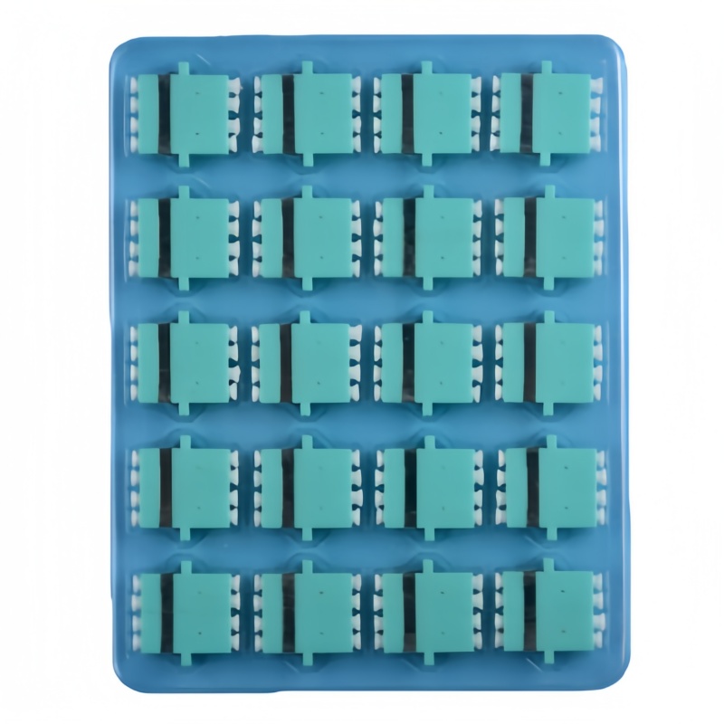
Zone Specification Checklist
Each zone has its own procurement list. Combine these into a single RFQ and the supplier can quote a coherent system instead of a box of parts.
| Zona | Specify this | Por que isso é importante |
|---|---|---|
| ER | OS2 single-mode backbone, MPO-12 or MPO-24, carrier handoff panel | Carrier demarcation is the boundary of responsibility; panels must match carrier connector form |
| MDA | High-density ODF/cassette frame, OS2 to HDA, MPO-24 trunks, 800 mm cabinet | Central cross-connect; any density shortfall propagates to every row |
| IDA | OS2 single-mode spine, MPO-24 or MPO-32, splicing and cross-connect capacity | Intermediate aggregation prevents an unmanageable star from the MDA |
| HDA | OM4/OM5 row trunks to EDA, LC duplex patch fields, MPO-LC cassettes, 800 mm cabinet | Row transition point; polarity and labeling discipline start here |
| ZDA | Consolidation enclosure, no active gear, pre-terminated trunk + short patch cords | Reconfiguration point; must not host cross-connects per TIA-942-C |
| EDA | Cat6A/DAC for management, LC duplex fiber patch cords, 1U horizontal managers | Most moves happen here; poor cable management becomes a daily operational cost |
The checklist also needs a test column. Every backbone and horizontal fiber link should be certified with Tier 1 optical loss test set measurements against the application loss budget. Backbone OS2 and any link supporting 400G/800G should add Tier 2 OTDR testing, with end-face inspection to IEC 61300-3-35 antes do acasalamento.
When should a data center use OS2 everywhere instead of OM4?
Use OS2 when the final distance or speed is uncertain, when the facility may expand across a campus, or when 800G/1.6T beyond SR8 reach is expected. OM4/OM5 is cheaper on a per-transceiver basis for short-reach 100G/400G inside a row, but a future speed upgrade can force recabling if the reach or fiber count is exhausted.
Does TIA-942-C require MPO-16 for 800G?
800GBASE-SR8 uses eight lanes in each direction, or sixteen fibers total, so the optical interface is MPO-16. TIA-942-C recognizes higher-fiber-count MPO variants for AI clusters. Some operators spec MPO-24 trunks now so the same cable can carry 800G SR16 and future 1.6T paths with a cassette swap.
What is the practical horizontal cable length limit?
TIA-568 limits the copper channel to 100 m, of which 90 m is permanent link and 10 m is patch cord. Fiber horizontal runs are limited by the application loss budget, not a fixed meter cap; OM4 holds 100 m at 100G/400G/800G SR, while OS2 effectively removes the distance constraint inside one building.
How much tray fill should be left for growth?
Design to 50% fill per TIA-942-C, and hand over at 40% or less. This leaves room for the expansion that always comes within the first two years without requiring a new tray run.
Should redundant pathways share the same overhead tray?
No. TIA-942 Rated 3 and Rated 4 require physically separated primary and alternate pathways. Running both paths in the same tray defeats concurrent maintainability and fault tolerance; it is one of the most common certification failures.
Fenxi supplies the passive layer that sits between these zones: MPO/MTP trunk cables, Quadros de distribuição ODF, LC/SC/MPO adapter panels e single-mode and multimode patch cords for the zone-to-zone runs, plus splice trays for campus extensions. Send the zone plan, reach table and target application, and we will return a Bill of Materials with the right connector counts, polarity and loss budget before you order. For 400G MPO trunk specifics, see our earlier MPO/MTP trunk cable for 400G guide.