
The last two meters of an FTTH link decide more margin than most bills of materials admit. When the drop cable reaches the subscriber wall, a crew either locks a field installable connector onto the fiber in under two minutes or unpacks a fusion splicer and welds on a factory pigtail. Both routes end in a working SC/APC port, but they differ in optical loss, capital equipment, crew training and long-term behaviour under heat and vibration — and one default applied across an entire rollout turns into either blown loss budgets or splicer crews queued at subscriber doors.
How the Two Termination Methods Actually Work
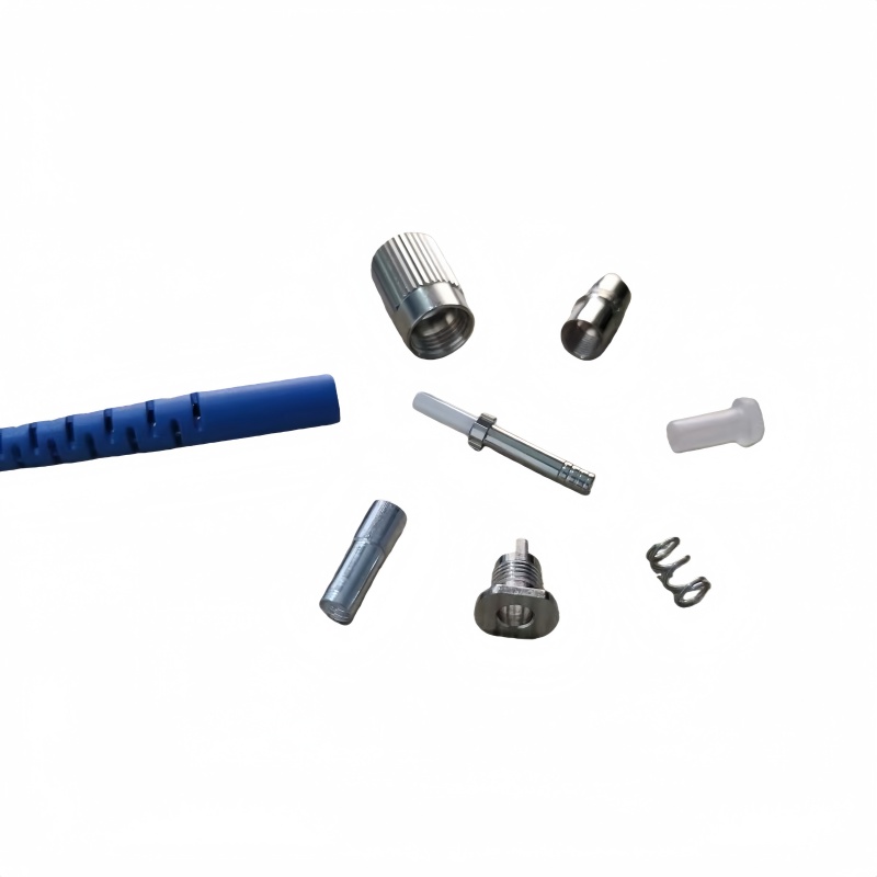
A field installable connector — often listed as a fast connector or mechanical splice-on connector — carries a factory-polished fiber stub set permanently inside the ferrule. The technician strips the drop cable, cleaves the field fiber to a set length, inserts it against that stub and cams a V-groove clamp shut. An index-matching gel between the two glass ends suppresses reflection at the mechanical joint. No epoxy, no polishing puck, no electrical arc: the whole operation runs on a stripper, a cleaver and a visual fault locator.
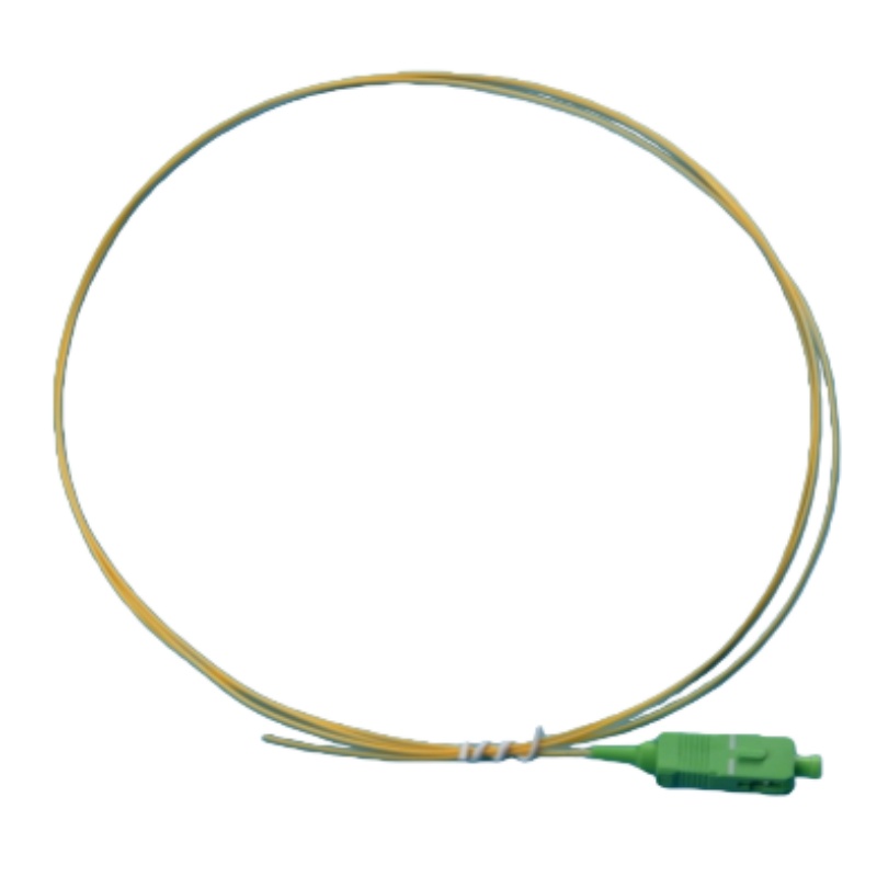
Fusion splicing to a pigtail takes the other road. The field cable is cleaved and arc-welded to a 0.9 mm pigtail — a short fiber length factory-terminated with a connector at one end, like the pigtails Fenxi terminates in-house — and the joint is protected in a heat-shrink sleeve before the pigtail connector lands in the adapter. The splice itself is glass fused to glass, with no gel and no clamp, and the splicer’s loss estimate routinely reads 0.05 dB or better.
| Parâmetro | Field installable connector | Fusion splice to pigtail |
|---|---|---|
| Joint construction | Pre-polished factory stub + V-groove clamp + index-matching gel | Arc-welded glass joint under a heat-shrink sleeve |
| Perda de inserção típica | 0.3 dB typical, 0.5 dB maximum | 0.05–0.1 dB |
| Perda de retorno | ≥45 dB UPC / ≥55 dB APC at the connector | Set by the pigtail connector: ≥55 dB APC typical |
| Time per termination | 1–2 minutes | 3–8 minutes including sleeve shrink |
| Field equipment | Stripper, cleaver, VFL | Fusion splicer, cleaver, stripper, heat oven, power |
| Re-termination | Unscrew and replace the connector | Cut the fiber back and re-splice |
The Loss Numbers to Write Into the Specification
The two numbers that matter are insertion loss and return loss, and they are not symmetric between the methods. Insertion loss on a field installable connector is dominated by the mechanical joint: a good cleave and a clean fiber land near 0.3 dB, a poor one pushes toward the 0.5 dB ceiling. Test each mated pair to IEC 61300-3-4 at 1310 and 1550 nm, and treat the vendor’s “typical” figure as a marketing number until the acceptance data says otherwise.
Return loss is where the polish and the joint both show up. A UPC fast connector should hold ≥45 dB and an APC version ≥55 dB when measured per IEC 61300-3-6, and the APC value is the one that catches a wrong-angle polish or a dry gel joint. On a PON drop the budget is already tight by design: ITU-T G.984.2 allows 13–28 dB for Class B+ ODNs, and the customer drop carries only two mated connections, so an extra 0.3 dB at the wall rarely sinks a link on its own. The place the difference compounds is a long cascade of field joints between the OLT and the splitter, which our PON power budget guide works through number by number, and the loss budget method published by the Fiber Optic Association is a practical template for the whole calculation.
Cleave quality and contamination decide most of the spread between a 0.3 dB and a 0.5 dB fast connector. The cleave angle and how far the fiber sits into the V-groove are fixed by the connector design, so crews should follow the manufacturer’s stated cleave length instead of improvising, and every terminated joint should get a visual fault locator check before the acceptance meter comes out. Contamination is the other half of the number: the factory stub arrives capped, the field fiber does not, and one unwiped cleave puts skin oils exactly where the gel has to carry the optical interface. Inspection discipline at the moment of termination costs minutes and removes a whole class of handover disputes before they start.
Where Each Method Belongs in the Network
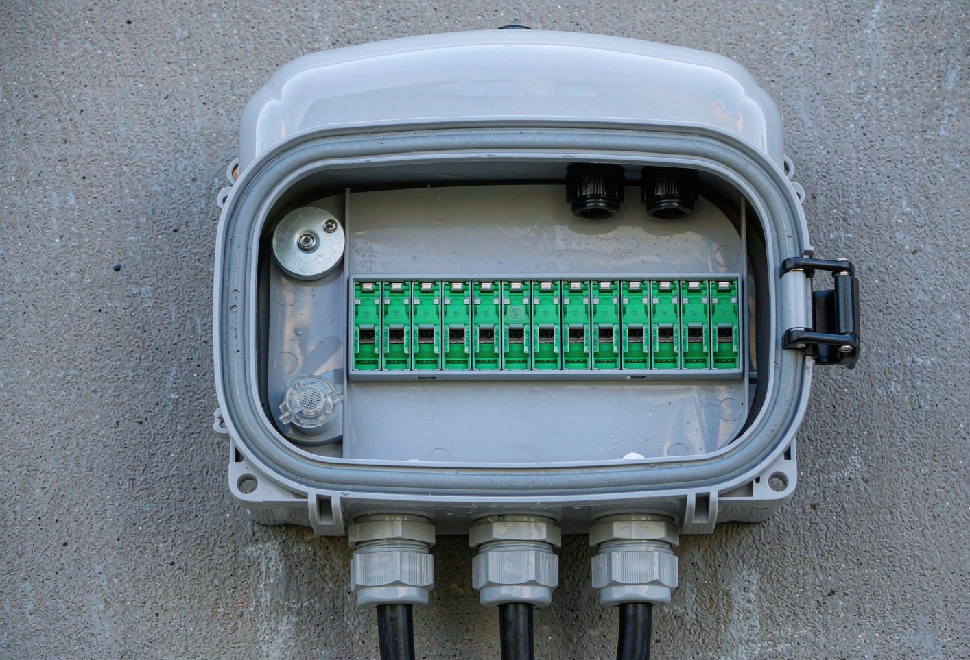
Treating the choice as per-segment instead of site-wide is what separates the operators with clean acceptance records from the ones with repeat fault calls. Indoors, in a sealed enclosure, protected from weather and UV, a field installable connector is the faster and cheaper answer with no reliability penalty worth arguing about. Outdoors, at an aerial closure or a splitter cabinet that will not be opened again for years, the fusion splice holds a real edge because there is no gel to age and no clamp to creep.
| Network segment | Recommended method | Why |
|---|---|---|
| Indoor drop to the ONT | Field installable SC/APC | Minutes per unit, no power, protected environment |
| MDU activation day | Field installable | Per-unit speed compounds across dozens of units in one visit |
| Wall-mount termination box at the building entrance | Either, if the box is sealed | A gasketed enclosure protects the gel joint from weather |
| Aerial closures and splitter cabinets | Fusion splice to pigtail | Heat, UV and vibration age gel and shift V-grooves |
| Feeder and backbone cables | Fusion splice | Loss accumulates over cascaded joints; lowest loss wins |
| Emergency restoration | Field installable now, splice later | Service returns the same day; permanent joint at the next window |
Gel, Heat and the Five-Year Question
The performance gap between the two methods widens with time, not on day one. The index-matching gel inside a fast connector ages under thermal cycling and the V-groove mechanism can shift under vibration; installers in the Middle East and sub-Saharan Africa have reported loss creep on exposed fast connectors years before the same joints would be revisited indoors. A fusion splice has none of those parts, which is why a joint protected in a quality sleeve and organized in a splice tray outlasts the cable around it.
That is an argument for matching the method to the enclosure, not for abandoning fast connectors. Terminations inside a gasketed caixa de terminação de fibra see nothing like the thermal swing of an exposed pedestal, and Telcordia GR-326-CORE qualification — temperature cycling, damp heat, vibration, mechanical durability — is the benchmark that separates qualified designs from cheap copies. Ask vendors for the change in insertion loss and return loss after each environmental test; a part that drifts 0.2 dB through a cycling test is telling you what it will do on the wall.
The Cost Math Behind the Two Trucks
Labor dominates FTTP deployment cost — industry estimates put it around 80 per cent of the build — so the per-termination consumable difference between a fast connector and a splice sleeve is rarely the deciding number. What swings the math is minutes: a crew activating 15–25 drops per day with fast connectors skips the splicer setup, the power hunt and the tray routing entirely, and project teams that moved drop terminations from pigtail splicing to fast connectors have reported activation timelines compressing by a third or more. The fusion splicer itself costs thousands of dollars and only amortizes across hundreds of joints, which is why it pays for itself at the feeder and distribution layers and idles at the subscriber door.
The second cost line is rework. A failed fast connector is a two-minute fix — pull, re-cleave, re-insert — while a bad splice means a second truck roll with the splicer. Against that, fast connectors are mostly single-use: a re-cleaved fiber in a spent V-groove will not meet the same loss figure, so the crew has to stock spares. Churn-heavy MDU stock adds one more factor, because a connector that can be replaced without touching the splice closure keeps moves and changes off the splicing calendar. The operators with the tightest unit economics run both methods deliberately and write the boundary into the cable schedule.
Five Pitfalls That Cost Real Money
Most of the expensive failures we see quoted for repair follow a handful of patterns, and every one of them is preventable on paper before a crew leaves the depot.
| Armadilha | Symptom on site | Prevenção |
|---|---|---|
| One method everywhere | Crews splicing indoor drops, or fast connectors inside street closures | Write the method per segment into the cable schedule |
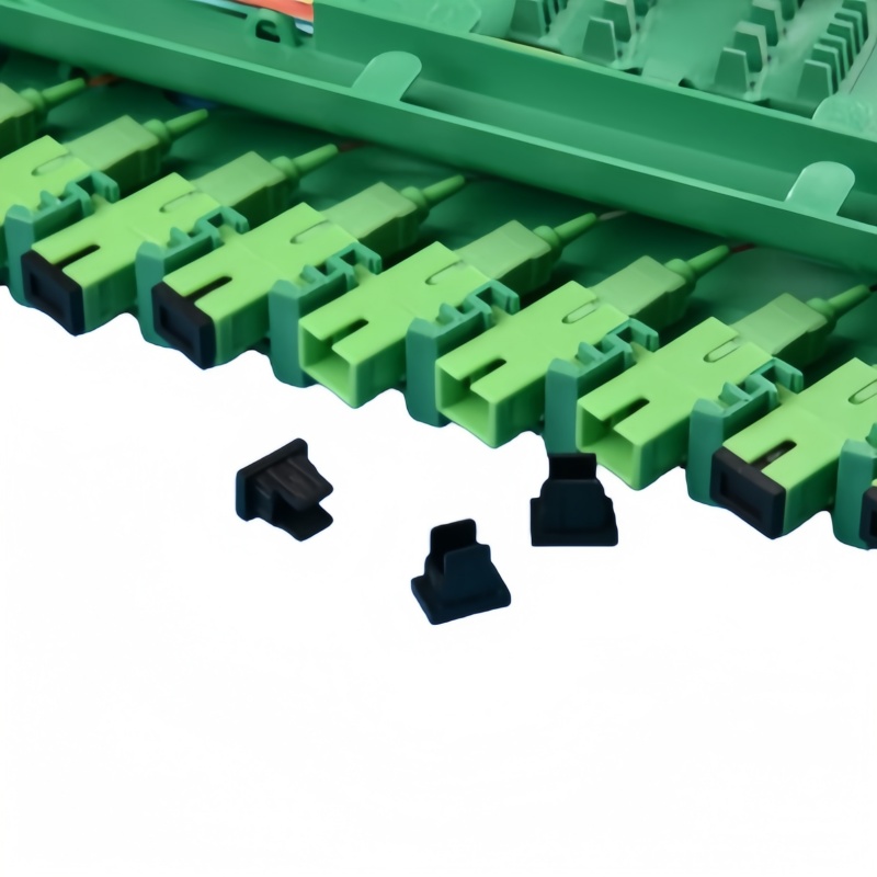
| UPC and APC mixed on the drop | A blue cord on a green port leaves a wedge air gap and a repeat fault call | Keyed green adapters and a single written polish rule |
| Wrong buffer prepared | 250 µm fiber jammed into a 900 µm port, or a loose fit that misaligns | Order connectors matched to the cable build and stock both SKUs |
| Return-loss test skipped on APC fast connectors | A dry gel joint or wrong-angle polish passes an insertion-loss-only check | 100 % IL + RL test per IEC 61300-3-6 before handover |
| Reusing single-use connectors | Re-cleaved fibers in spent V-grooves drifting past the loss limit | Treat mechanical connectors as single-use and carry spares |
End-face quality ties into the same discipline: a dirty or over-pressured ferrule fails the same acceptance test no matter how it was terminated, so put the inspect-before-you-connect routine from Fluke Networks into the work instruction, and let TIA intermateability standards settle any dispute over mixed-vendor matings. Fenxi supplies both routes from the same production lines — Conectores SC assembled as fast connectors for drop terminations, and factory pigtails and patch cords for splice-based builds — with insertion and return loss recorded per assembly. Send your cable schedule, drop volumes and target loss limits, and our engineers will price the termination mix against your rollout plan.