Giriş: Sinyal Bütünlüğünün Sessiz Koruyucusu
Fiber optik iletişim dünyasında konektörler, bir sinyalin sağlam bir şekilde ulaşıp ulaşmadığını veya gürültüye dönüşüp dönüşmediğini belirleyen kritik arayüzler olan isimsiz kahramanlardır. Günümüzde mevcut olan düzinelerce konnektör tipi ve cila stili arasında, uygulama tavizsiz sinyal kalitesi gerektirdiğinde bir kombinasyon öne çıkar: APC (Açılı Fiziksel Temas) cilalı SC (Abone Konnektörü).
Standart konnektör ile SC APC konnektörü arasındaki fark ince görünebilir. Her ikisi de fiber çekirdekleri hizalayan küçük plastik veya metal halkalardır. Her ikisi de ışığın bir fiberden diğerine geçmesini sağlar. Ancak analog ve yüksek hassasiyetli optik ağlarda - her desibelin önemli olduğu, yansıyan ışığın lazerlerin dengesini bozabildiği ve sinyalleri bozabildiği ve ölçüm doğruluğunun çok önemli olduğu yerlerde - konektör cilası seçimi, kusursuz performans gösteren bir ağ ile sertifikasyonda başarısız olan bir ağ arasındaki fark anlamına gelebilir.
Binlerce aboneye 110 kanal analog video sağlayan bir CATV ağını düşünün. Zayıf geri dönüş kaybına sahip tek bir konnektör hayalet görüntüler oluşturabilir, taşıyıcı-gürültü oranını düşürebilir ve izole edilmesi neredeyse imkansız olan müşteri şikayetlerine neden olabilir. Bir fiber açıklığını metrenin altında bir hassasiyetle karakterize etmeye çalışan bir optik zaman alanı yansıtma ölçer (OTDR) düşünün. Aşırı yansıma üreten bir konnektör, cihazı körleştirerek kritik olayları gizleyen “ölü bölgeler” yaratabilir. Tutarlı bir optik iletişim sistemi veya interferometrik sensör dizisi düşünün - faz kararlılığının her şey olduğu uygulamalar. Burada, geri yansımalar dar hat genişlikli lazerlerin dengesini bozabilir ve ölçüm verilerini bozabilir.
Tüm bu senaryolarda, SC APC konnektörü birçok seçenek arasında bir seçenek olarak değil, temel seçim olarak ortaya çıkmaktadır. Sağlam SC form faktörü ve 8 derecelik açılı cilanın üstün geri dönüş kaybı özelliklerinin birleşimi, onu hassasiyet, kararlılık ve sinyal doğruluğundan ödün verilemeyecek uygulamalar için benzersiz bir şekilde uygun hale getirir.
Bu kapsamlı kılavuz, SC APC konnektörlerinin analog ve yüksek hassasiyetli optik ağlarda neden vazgeçilmez hale geldiğini araştırıyor. APC'ye avantaj sağlayan fiziği, buna bağlı olan gerçek dünya uygulamalarını, benimsenmesini sağlayan pazar güçlerini ve mühendislerin ve teknisyenlerin bu konektörleri etkili bir şekilde dağıtmak için anlaması gereken pratik hususları inceleyeceğiz.
Bölüm 1: SC APC Konnektörünü Anlama
1.1 SC Konnektör Nedir?
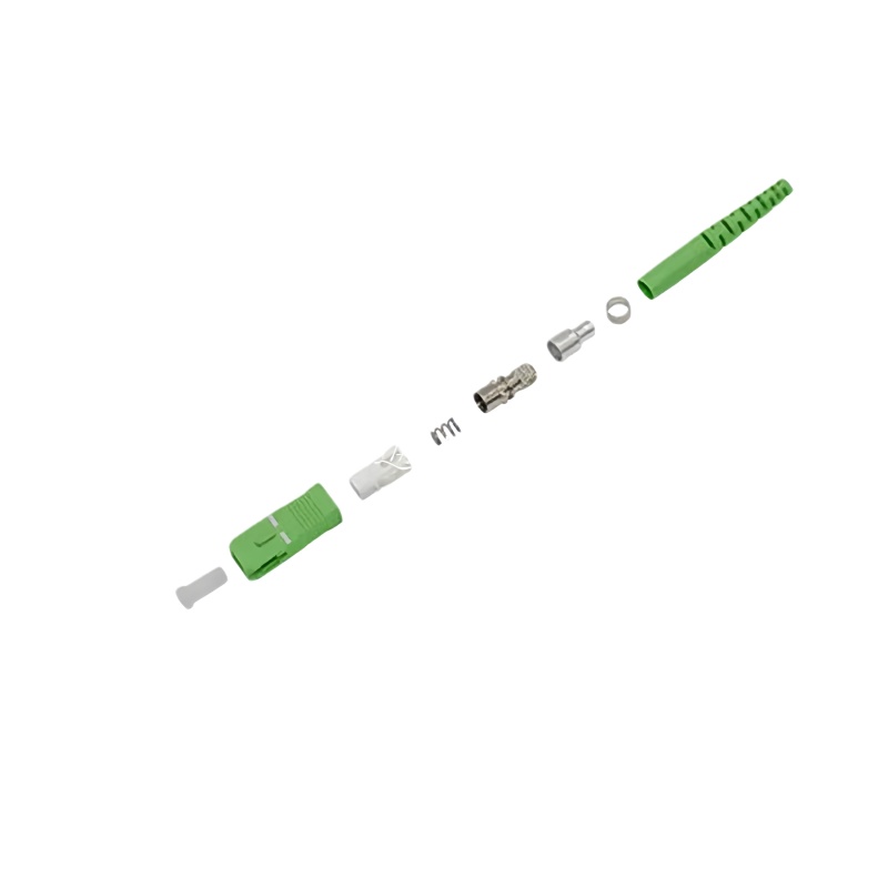
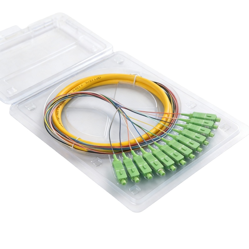
SC (Abone Konektörü), 1980'lerin ortalarında Nippon Telegraph and Telephone (NTT) tarafından, ilk fiber dağıtımlarına hakim olan vidalı FC konektörüne uygun maliyetli, kullanıcı dostu bir alternatif olarak geliştirilmiştir. Belirleyici özellikleri arasında kare, itme-çekme mandallama mekanizması, 2,5 mm seramik yüksük ve dünya çapında fiber teknisyenleri tarafından anında tanınan kalıplanmış plastik bir muhafaza bulunmaktadır.
SC konnektörün tasarımı, daha önceki konnektör türlerini rahatsız eden çeşitli pratik endişeleri giderir. İtme-çekme mekanizması, eşleştirme sırasında konnektör gövdesini döndürme ihtiyacını ortadan kaldırır; bu da parmak erişiminin sınırlı olduğu yoğun yama panellerinde önemli bir avantajdır. Kare gövde pozitif yönlendirme sağlar ve dönmeyi önleyerek tutarlı hizalama sağlar. Ve mandalın duyulabilir “klik” sesi, uygun bir bağlantının yapıldığına dair dokunsal bir onay sağlar.
Bu özellikler SC konnektörünü 1990'lar boyunca ve 2000'lerin başında telekomünikasyon uygulamaları için baskın seçenek haline getirmiştir. LC gibi daha küçük form faktörlü konnektörlerin yaygınlaştığı günümüzde bile SC; erişim ağlarında, CATV sistemlerinde ve sağlamlık ve güvenilirliğinin yoğunluktan daha değerli olduğu test ekipmanlarında yaygın olarak kullanılmaya devam etmektedir.
SC konektörü, SC tipi konektör ailesi için standart arayüz boyutlarını tanımlayan IEC 61754-4 standardına uygundur. Bu standardizasyon, farklı üreticilerin bileşenleri arasında birlikte çalışabilirliği sağlar ve performans beklentileri için bir temel oluşturur.
1.2 “APC” Tanımlaması: Açılı Fiziksel Temas Ne Anlama Geliyor?
“APC” tanımı, yüksük uç yüzüne uygulanan cilayı, yani fiber ekseninin dik düzlemine göre 8 derecelik bir açıyı ifade eder. Görünüşte basit olan bu geometrik değişikliğin konnektör performansı üzerinde derin etkileri vardır.
Bunun nedenini anlamak için öncelikle ışık fiberden fibere bir arayüzle karşılaştığında ne olduğunu anlamamız gerekir. Herhangi bir konektörde, cam-hava-cam arayüzünde meydana gelen Fresnel yansıması nedeniyle az miktarda ışık kaynağa doğru geri yansıtılır. Bu yansımanın büyüklüğü, fiber çekirdek ile eşleştirilmiş konektörler arasındaki hava boşluğu (veya indeks eşleştirme malzemesi) arasındaki kırılma indisi uyumsuzluğuna bağlıdır.
Bir PC (Fiziksel Temas) veya UPC (Ultra Fiziksel Temas) konnektöründe, yüksük uç yüzü fiber eksenine dik olarak parlatılır. Bu, yansıyan herhangi bir ışığın doğrudan fiber çekirdeğinden kaynağa doğru geri gittiği anlamına gelir; bu, geri yansıma olarak bilinen bir olgudur. Bir APC konnektöründe 8 derecelik açı, yansıyan ışığın toplam iç yansıma için kritik açıdan daha büyük bir açıyla fiber kaplamaya yönlendirilmesini sağlar. Bu yansıyan ışık daha sonra kaplama boyunca ilerlerken hızla zayıflatılır ve bir girişim kaynağı olarak etkili bir şekilde ortadan kaldırılır.
APC konnektörü, eğik açı 8 dereceden fazla olduğunda -60 dB'den daha az olmak üzere son derece düşük geri yansıma elde etmek için özel olarak geliştirilmiştir. Bu, yansıyan güçte bir PC konnektörüne kıyasla en az üç büyüklük mertebesinde ve bir UPC konnektörüne kıyasla en az bir büyüklük mertebesinde bir azalmayı temsil eder.
1.3 Fiziksel Özellikler ve Görsel Tanımlama
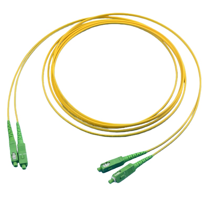
SC APC konnektörleri görsel olarak ayırt edicidir, bu da sahada maliyetli yanlış eşleştirme hatalarını önlemeye yardımcı olur. Sektör, APC cilasını belirtmek için konektör gövdesi ve adaptör muhafazası için yeşil renk kodunu standartlaştırmıştır. Buna karşılık, UPC konnektörleri tipik olarak mavi, PC konnektörleri (öncelikle çok modlu uygulamalar için) ise genellikle bej veya siyahtır.
Bu renk kodlaması sadece estetik değildir; kritik bir güvenlik ve performans işlevine hizmet eder. Bir APC konnektörün bir UPC konnektörle eşleştirilmesi açılı yüksük uç yüzüne zarar verebilir, aşırı ekleme kaybı yaratabilir ve APC kullanım amacını ilk etapta ortadan kaldıran yüksek geri yansıma oluşturabilir. Yeşil renk, teknisyenlerin uygun eşleşme uyumluluğunu doğrulamak için kullanabilecekleri anında görsel bir ipucu sağlar.
Yüksüğün kendisi tipik olarak zirkonya seramikten üretilir ve sertliği, boyutsal kararlılığı ve barındırdığı silika elyafınkine yakın termal genleşme özellikleri nedeniyle seçilir. Yüksek hassasiyetli üretim, fiber çekirdeğin yüksük içinde mikron altı toleranslar dahilinde merkezlenmesini ve 8 derecelik cila açısının tüm uç yüz boyunca tutarlı bir şekilde korunmasını sağlar.
Bölüm 2: Performans Fiziği - APC Neden Önemlidir?
2.1 Geri Dönüş Kaybı: Kritik Parametre
Geri dönüş kaybı, analog ve yüksek hassasiyetli ağlarda kullanılan konnektörler için tartışmasız en önemli özelliktir. Yansıyan optik gücün gelen optik güce oranını ölçer ve desibel (dB) cinsinden ifade edilir. Daha yüksek bir geri dönüş kaybı değeri, daha düşük yansımayı gösterir; -60 dB'lik bir geri dönüş kaybı, gelen gücün yalnızca 0,0001%'sinin kaynağa doğru geri yansıtıldığı anlamına gelir.
Tablo 1: Konektör Cila Tipine Göre Geri Dönüş Kaybı Özelliklerinin Karşılaştırılması
| Konektör Cila Tipi | Tipik Geri Dönüş Kaybı (dB) | Yansıtılan Güç (%) | Uygulamalar |
|---|---|---|---|
| PC (Fiziksel Temas) | -30 ila -40 | 0,1% ila 0,01% | Eski çok modlu, bazı tek modlu |
| UPC (Ultra Fiziksel Temas) | -40 ila -55 | 0.01% ila 0.0003% | Dijital telekom, veri merkezleri |
| APC (Açılı Fiziksel Temas) | -60 ila -70+ | 0.0001% ila 0.00001% | Analog video, RFoF, test ekipmanları, yüksek güç |
Kaynaklar: Endüstri standartları ve üretici spesifikasyonları
UPC ve APC arasındaki fark desibel cinsinden ifade edildiğinde küçük görünebilir -50 dB'ye karşı -65 dB gibi. Ancak desibel ölçeği logaritmiktir, yani 15 dB'lik bir iyileşme yansıyan güçte yaklaşık 97%'lik bir azalmayı temsil eder. Bu ince bir fark değil; dönüştürücü bir fark.
Endüstri standartları, minimum geri dönüş kaybı gereksinimleri konusunda net bir rehberlik sağlar. Sektörün tavsiyesi, UPC konnektör geri dönüş kaybının -50 dB veya daha fazla olması, APC konnektör geri dönüş kaybının ise -60 dB veya daha fazla olmasıdır. Diamond gibi üreticilerin birinci sınıf APC konnektörleri, tek modlu APC tipleri için 70 dB'nin üzerinde geri dönüş kaybına ulaşır ve ekleme kaybı 0,2 dB'nin altındadır.
2.2 Ekleme Kaybı: Performans Dengesi
Geri dönüş kaybı APC konnektörleri için en önemli özellik olsa da, ekleme kaybı (bağlantı boyunca kaybedilen optik güç miktarı) genel bağlantı bütçesi değerlendirmeleri için eşit derecede önemlidir. APC konnektörler tipik olarak 0,2 dB ila 0,5 dB aralığında ekleme kaybı sergiler ve premium konnektörler 0,2 dB'nin altında değerler elde eder.
Açılı cila, ışık yolunun açılı arayüzde hafifçe kırılması gerektiğinden, dik cilalara kıyasla hafif bir geometrik verimsizlik ortaya çıkarır. Bu durum, APC konnektörlerin UPC muadillerine kıyasla marjinal olarak daha yüksek tipik ekleme kaybını açıklamaktadır. Bununla birlikte, uygulamaların büyük çoğunluğu için bu küçük ek kayıp, geri dönüş kaybındaki çarpıcı iyileşme ile fazlasıyla dengelenmektedir.
Tablo 2: Önde Gelen Üreticilerin Tipik SC APC Konnektör Özellikleri
| Parametre | Standart Sınıf | Premium/ULL Sınıf | Test Koşulları |
|---|---|---|---|
| Ekleme Kaybı (tipik) | ≤ 0,3 dB | ≤ 0,2 dB | Eşleştirilmiş çift başına, 1310/1550 nm |
| Ekleme Kaybı (maksimum) | 0,5 dB | 0,34 dB | Çiftleşen çift başına |
| Geri Dönüş Kaybı (minimum) | 55-60 dB | 65-70+ dB | Tek modlu |
| Geri Dönüş Kaybı (tipik) | 60-65 dB | 70+ dB | Tek modlu |
| Dayanıklılık | ≥ 500 döngü | ≥ 1000 döngü | Değişim < 0,2 dB |
| Çalışma Sıcaklığı | -40°C ila +85°C | -40°C ila +85°C | IEC 61753-1'e göre |
Kaynaklar: Üretici veri sayfaları ve endüstri standartlarının derlenmesi
2.3 8 Derecelik Açı: Dikkatle Tasarlanmış Bir Uzlaşma
Neden 8 derece? Bu özel açı, fiber optik mühendislerinin onlarca yıldır rafine ettiği rakip gereksinimlerin bir optimizasyonunu temsil eder.
Açı çok sığ olsaydı (yaklaşık 6 dereceden az), yansıyan ışık, toplam iç yansıma ve hızlı zayıflama sağlamak için kaplamaya yeterince yönlendirilemezdi. Bir miktar ışık hala fiber çekirdeğe geri dönecek ve geri dönüş kaybı performansını tehlikeye atacaktır.
Açı çok dik olsaydı (yaklaşık 12 dereceden büyük), ışık yolu arayüzde daha dramatik kırılma gerektirdiğinden ekleme kaybı önemli ölçüde artardı. Ayrıca, üretim toleransları daha zorlu hale gelir ve eşleşme sırasında yüksük hasarı riski artar.
8 derecelik standart, kapsamlı araştırmalar ve pratik deneyimler sonucunda ortaya çıkmıştır. Bu açıda, geri yansıma -60 dB'den daha düşük bir seviyeye iner; bu da neredeyse tüm uygulamalar için bir endişe kaynağı olan geri yansımayı etkili bir şekilde ortadan kaldırır. Aynı zamanda, ekleme kaybı ağ tasarımlarının büyük çoğunluğu için kabul edilebilir sınırlar içinde kalır.
Sektör, APC konnektörleri için fiili standart olarak 8 derece etrafında birleşmiştir. Bu standardizasyon, farklı üreticilerin bileşenleri arasında birlikte çalışabilirliği sağlar ve tedarik zincirini basitleştirir.
Bölüm 3: Analog Optik Ağlarda SC APC
3.1 Analog İletimin Benzersiz Zorlukları
Analog optik iletim, konektör performansını (özellikle de geri dönüş kaybını) kritik derecede önemli kılan şekillerde dijital muadilinden temel olarak farklıdır.
Dijital bir sistemde, bilgi ayrık birler ve sıfırlar olarak kodlanır. Alıcının sadece iki durum arasında ayrım yapması gerekir. Sinyal-gürültü oranı bir eşiği aştığı sürece, alıcı verileri mükemmel bir şekilde kurtarabilir. Dijital karar eşiği doğal gürültü bağışıklığı sağladığından orta düzeyde yansıma, gürültü ve bozulma tolere edilir.
Analog sistemlerin böyle bir lüksü yoktur. İster kablolu televizyon sinyalleri, ister fiber üzerinden radyo frekansı (RFoF) veya hassas sensör verileri taşısın, analog bir optik bağlantıda bilgi doğrudan optik taşıyıcının genliği, fazı veya frekansında kodlanır. İletim ortamından kaynaklanan herhangi bir bozulma doğrudan bilgi içeriğini bozar. Dijital anlamda “hata düzeltme” yoktur; alıcıya ne ulaşırsa onu alırsınız.
Bu temel fark, analog ağların optik yansımalara karşı neden son derece hassas olduğunu açıklar. Kaynağa doğru geri dönen yansıyan ışık lazer boşluğu ile etkileşime girerek lazerin çıkış dalga boyu ve gücünde kararsızlığa neden olabilir. Optik geri besleme kaynaklı gürültü olarak bilinen bu olgu, artan bağıl yoğunluk gürültüsü (RIN) ve bozulmuş taşıyıcı-gürültü oranı (CNR) olarak kendini gösterir.
Ayrıca, bir fiber bağlantı boyunca çoklu yansımalar, sinyalin gecikmeli kopyalarının doğrudan sinyalin üzerine bindirilmiş olarak alıcıya ulaştığı bir sinyal bozulması biçimi olan çok yollu parazit (MPI) oluşturabilir. Analog sistemlerde MPI, videoda hayalet görüntüler, RF taşıyıcılarında bozulma ve kompozit ikinci dereceden (CSO) ve kompozit üçlü vuruş (CTB) performansında bozulma olarak ortaya çıkar.
3.2 CATV ve Geniş Bant Dağıtım Şebekeleri
Kablolu televizyon (CATV) ağları, analog optik iletim sistemlerinin dünyadaki en büyük dağıtım tabanlarından birini temsil etmektedir. Modern CATV mimarileri, optik fiberin sinyalleri merkezden mahalle düğümlerine taşıdığı ve koaksiyel kablonun abonelere nihai dağıtımı tamamladığı bir hibrit fiber-koaksiyel (HFC) topolojisi kullanır.
Bu ağlar için performans gereksinimleri zorludur. Tipik bir CATV optik bağlantısı 77 ila 110 kanal analog video (NTSC veya PAL formatlarında), artı dijital QAM taşıyıcıları ve DOCSIS veri sinyalleri taşımalıdır, bunların tümü tek bir optik dalga boyunda çoklanır - tipik olarak daha kısa bağlantılar için 1310 nm veya erbiyum katkılı fiber amplifikatörler (EDFA'lar) kullanılarak daha uzun açıklıklar için 1550 nm.
Bu sistemlerde CNR gereksinimleri katıdır. Tipik bir spesifikasyon, 0 dBm optik giriş gücüne sahip 77 NTSC kanalı için CNR ≥ 50 dB gerektirir. CSO ve CTB spesifikasyonları da benzer şekilde zorludur - tipik olarak sırasıyla ≥ 65 dB ve ≥ 60 dB. Bu performans seviyelerine ulaşmak için konektör yansımaları da dahil olmak üzere tüm sinyal bozulma kaynaklarının en aza indirilmesi gerekir.
SC APC konnektörleri CATV vericileri, optik düğümler ve pasif optik alıcılar üzerindeki optik arayüzler için belirlenmiştir. SC/APC - RF analog sinyal arayüzü, optik sinyalleri koaksiyel dağıtım için RF'ye dönüştüren FTTH CATV alıcılarında standarttır. Bu cihazlar çoğu durumda pasiftir - yani elektrik gücü olmadan çalışırlar, tamamen optik sinyalin kendisine güvenirler - bu da optik verimliliği ve düşük yansımayı daha da kritik hale getirir.
3.3 Fiber Üzerinden RF (RFoF) Uygulamaları
Fiber üzerinden RF teknolojisi CATV'nin çok ötesine uzanmaktadır. Radyo frekansı sinyallerinin mesafeler boyunca ve koaksiyel kablonun kabul edilemez kayıplara yol açacağı veya elektromanyetik parazitin sinyali bozacağı ortamlardan taşınmasını sağlar.
Temel RFoF uygulamaları şunları içerir:
Uydu İletişimi: L-bandı sinyallerini uydu çanak antenlerinden iç mekan alıcı ekipmanlarına taşıyarak uzun koaksiyel kabloların kayıplarını ve frekansa bağlı zayıflamalarını ortadan kaldırır.
Dağıtılmış Anten Sistemleri (DAS): Hücresel ve kamu güvenliği radyo sinyallerini baz istasyonlarından büyük binalar, kampüsler ve tüneller boyunca uzak anten birimlerine taşımak.
Radar ve Elektronik Harp: Koaksiyel kablo ağırlığının ve kaybının engelleyici olduğu askeri sistemlerde mikrodalga sinyallerinin dağıtımı.
Radyo Astronomi ve Bilimsel Enstrümantasyon: Son derece zayıf sinyallerin antenlerden işleme ekipmanına minimum bozulma ile taşınması.
Tüm bu uygulamalarda, tipik RFoF bağlantılarının geniş çalışma frekansı aralığı - genellikle 45 MHz'den 2400 MHz'e veya daha yükseğe kadar uzanır - olağanüstü doğrusallık ve düzlük gerektirir. Optik yol içindeki yansımalar, bağlantının transfer fonksiyonunda frekansa bağlı dalgalanmalar yaratarak düzlüğü bozabilir ve bozulmaya neden olabilir.
SC APC konnektörleri RFoF uygulamaları için fiili standart haline gelmiştir. Düşük geri yansıma özelliği lazer kararlılığını korurken, sağlam SC form faktörü sahada konuşlandırılan sistemlerde güvenilir performans sağlar. Birçok RFoF vericisi ve alıcısı, standart ekipman olarak SC/APC optik bağlantı noktaları ile tasarlanmıştır.
3.4 Gerçek Dünya Etkisi: CATV Performansında Bir Vaka Çalışması
Tek bir fiber üzerinden 500 aboneye hizmet veren tipik bir CATV optik bağlantısını düşünün. Bağlantı, merkezde bir verici, sahada bir 1×32 optik ayırıcı ve her biri yaklaşık 15 eve hizmet veren 32 optik düğüm içerir.
Bu bağlantı APC yerine UPC konnektörleri ile konuşlandırılmış olsaydı, çoklu yansımaların kümülatif etkisi çeşitli şekillerde ortaya çıkacaktı:
- Hayalet Görüntüler: İzleyiciler, özellikle metin taramaları veya istasyon logoları gibi yüksek kontrastlı içeriğe sahip kanallarda fark edilebilecek şekilde, ana görüntünün silik, kaydırılmış kopyalarını görebiliyordu.
- Bozulmuş CNR: Taşıyıcı-gürültü oranı 1-3 dB düşerek marjinal alıcıları kabul edilebilir görüntü kalitesi eşiğinin altına iter ve analog kanallarda gözle görülür “kar” oluşmasına neden olur.
- Artırılmış Bit Hata Oranı: Dijital QAM taşıyıcıları daha yüksek hata oranlarıyla karşılaşacak ve potansiyel olarak pikselleşmeye, makrobloklamaya veya dijital kanalların tamamen kaybolmasına neden olacaktır.
- Lazer Kararsızlığı: Verici lazer, tüm kanallardaki bozulmayı artıracak şekilde artan bağıl yoğunluk gürültüsüne maruz kalacaktır.
Bu sorunların teşhis edilmesi ve onarılması oldukça zordur. Aralıklı olarak ortaya çıkabilir, sıcaklığa göre değişebilir veya yalnızca belirli kanal dizilimleri kullanımdayken ortaya çıkabilir. Ağ tasarımcıları, SC APC konnektörlerini en baştan belirleyerek bu zorlu performans sorunlarının önemli bir kaynağını ortadan kaldırır.
Bölüm 4: Yüksek Hassasiyetli Optik Ağlarda SC APC
4.1 Optik Test ve Ölçüm Ekipmanı
Belki de hiçbir uygulama SC APC konnektörlerinin önemini optik test ve ölçümden daha açık bir şekilde gösteremez. Fiber ağları karakterize etmek için kullanılan cihazlar -OTDR'ler, optik kayıp test setleri, optik spektrum analizörleri ve geri dönüş kaybı ölçerler- test ettikleri cihazları aşan geri dönüş kaybı performansı sergilemelidir.
Bir OTDR, kısa optik darbeler göndererek ve geri saçılan ışığı analiz ederek bir fiber bağlantı boyunca olayların yansımasını ve zayıflamasını ölçer. Cihazın kendi konektör portları, aşırı yansıma üretirlerse hata kaynağı olabilirler. OTDR portundaki yüksek yansımalı bir konektör, cihazın alıcısını doyurabilecek büyük bir ilk yansıma yaratarak cihazın yakınında ilk birkaç metreden birkaç yüz metreye kadar fiberi gizleyen bir “ölü bölge” oluşturur.
Düzgün bağlanmış bir APC konnektör çifti, tipik olarak 0,5 dB'den daha az kayıp ve -55 dB ila -65 dB yansıtma ile yansıtıcı bir olay oluşturacaktır. Bu düşük yansıma, doğru OTDR ölçümleri ve zayıflama ölü bölgelerinin en aza indirilmesi için gereklidir. Birçok OTDR üreticisi, bu yakın uç etkilerini en aza indirmek için cihazlarını özellikle APC portları ile yapılandırır.
Hassas geri dönüş kaybı ölçüm cihazlarındaki açılı tek modlu test portu, 50 dB'ye kadar geri dönüş kaybı ölçümleri için harici sonlandırma gerektirmeden son derece hassas geri dönüş kaybı ölçümlerini garanti eder. Bu özellik, katı geri dönüş kaybı spesifikasyonlarını karşılaması gereken bileşenleri karakterize etmek için çok önemlidir.
4.2 İnterferometrik Algılama ve Metroloji
İnterferometri - iki ışık dalgası üst üste bindirildiğinde oluşan girişim deseninden bilgi çıkarma tekniği - bilimin bildiği en hassas ölçümlerden bazılarını mümkün kılmaktadır. Fiber optik interferometreler, petrol ve gaz aramadan köprü ve binaların yapısal sağlık izlemesine kadar çeşitli uygulamalarda gerinim algılama, sıcaklık izleme, akustik algılama ve hassas metroloji için kullanılır.
Bu sistemler optik faza karşı son derece hassastır. Algılama fiberine geri dönen herhangi bir istenmeyen yansıma, ölçüm sinyalini bozan parazit parazitler oluşturabilir. APC konnektörlerinin tipik olarak -65 dB'yi aşan yüksek geri dönüş kaybı, interferometrik uygulamalar için gereken faz saflığını korumak için gereklidir.
İnterferometrik ölçüm sistemleri yüksek kaliteli konnektörlere dayanır. Yüksük yüzeyinin kalitesi, optik konnektörlerin zayıflama ve yansıtma gibi iletim parametreleri üzerinde önemli etkiye sahiptir. İnterferometrik teknikler kullanılarak SC-APC konnektörleri için küresel yükseklik ve tepe ofseti ölçümleri, yüksük geometrisi ile konnektör performansı arasındaki kritik ilişkiyi göstermiştir.
4.3 Yüksek Güçlü Optik Sistemler
Raman amplifikatörleri, yüksek güçlü EDFA'lar ve endüstriyel lazer sistemleri gibi optik güç seviyeleri arttıkça, konektör performansı basit optik özelliklerin ötesinde ek boyutlar kazanır. Yüksek optik güç, fiber konnektörlerde çeşitli arıza mekanizmalarına neden olabilir:
Elyaf Uç Yüzü Hasarı: Konektör uç yüzeyindeki kirlenme optik gücü ve ısıyı hızla emerek cam yüzeyde lokal erimeye veya kırılmaya neden olabilir.
Termal Kaçak: Eşleştirilmiş fiberler arasındaki zayıf fiziksel temas, yüksek optik güç altında iyonize olabilen ve fiber uç yüzüne zarar veren bir plazma oluşturabilen bir hava boşluğu yaratır.
Konektör Gövdesi Isıtma: Fiberin kendisi sağlam kalsa bile, konektör gövdesi saçılan ışığı emebilir ve malzeme değerlerini aşan sıcaklıklara kadar ısınabilir.
APC konnektörleri yüksek güçlü uygulamalar için doğal avantajlar sunar. Açılı uç yüz, arayüzde yansıyan ışığın kaynağa doğru değil kaplamaya doğru yönlendirilmesini sağlayarak optik geri beslemeden kaynaklanan lazer hasarı riskini azaltır. Fiziksel temas tasarımı, temiz uç yüzeylerle düzgün bir şekilde eşleştirildiğinde, termal kaçağa yol açabilecek hava boşluğunu en aza indirir.
Araştırmalar, SP/APC konnektörlerinin, uç yüzeylerin temiz kalması koşuluyla, 22 dBm'ye (yaklaşık 160 mW) kadar yüksek optik güç altında optik hasar olmadan tekrarlanan bağlantı ve bağlantı kesme işlemlerine dayanabileceğini göstermiştir. Ancak, optik güç taşıyan konektörlerin temizlenmesi için gücün 15 dBm'yi (yaklaşık 32 mW) aşmayacak uygun bir seviyeye düşürülmesi önerilir.
Daha da yüksek güç uygulamaları için özel olarak tasarlanmış yüksek güçlü SC konnektörler mevcuttur. Bunlar, standart konnektör değerlerini çok aşan güç seviyelerine dayanmak için genişletilmiş ışın teknolojisi, gelişmiş termal yönetim ve özel uç yüz işlemleri gibi özellikler içerir.
4.4 Tutarlı Optik İletişim Sistemleri
Bilginin optik taşıyıcının hem genliğinde hem de fazında kodlandığı tutarlı optik iletişim, yüksek kapasiteli fiber iletiminin en ileri noktasını temsil eder. 400G, 800G ve yeni ortaya çıkan 1.6T veri hızlarında çalışan modern uyumlu sistemler DP-QPSK, DP-16QAM ve DP-64QAM gibi gelişmiş modülasyon formatlarına dayanmaktadır.
Bu sistemler faz gürültüsüne karşı son derece hassastır. Lazer boşluğuna yeniden giren herhangi bir yansıma lazerin fazını bozabilir ve alıcının sinyali doğru bir şekilde demodüle etme yeteneğini azaltan faz gürültüsünü ortaya çıkarabilir. Koherent sistemlerde kullanılan dar hat genişlikli lazerler (genellikle 100 kHz'in altındaki hat genişlikleriyle) optik geri beslemeye karşı özellikle hassastır.
Koherent sistemler modülasyonlarında ağırlıklı olarak dijital olsa da, faza duyarlı algılamanın altında yatan fizik, yansımalara duyarlılık söz konusu olduğunda daha çok analog sistemler gibi davranmalarına neden olur. SC APC konnektörleri, yüksek geri dönüş kaybı ve istikrarlı performanslarıyla, tutarlı sistemlerin gerektirdiği faz istikrarını korumak için gereklidir.
Bölüm 5: SC APC ve Alternatifleri - Karşılaştırmalı Bir Analiz
5.1 PC, UPC ve APC: Polonya Spektrumu
Üç ana konnektör cila tipi (PC, UPC ve APC), performans ve maliyet dengelerini temsil eder. Bu farklılıkları anlamak, bilinçli konnektör seçimleri yapmak için çok önemlidir.
PC (Fiziksel Temas): Tek modlu fiber için orijinal konektör cila tasarımı. Yüksük uç yüzü, fiber çekirdekler arasında fiziksel temas sağlamak için hafif bir küresel eğrilikle parlatılır ve erken düz cila konektörlerini rahatsız eden hava boşluğunu ortadan kaldırır. PC konnektörleri, birçok çok modlu uygulama ve eski tek modlu sistemler için yeterli olan -30 ila -40 dB'lik geri dönüş kaybına ulaşır. Günümüzde yeni tek modlu dağıtımlar için nadiren belirtilmektedirler.
UPC (Ultra Fiziksel Temas): Daha rafine cilalama teknikleri ve daha sıkı geometrik toleranslarla elde edilen PC cilasının bir evrimi. Geliştirilmiş yüzey kalitesi ve daha hassas eğrilik yarıçapı -40 ila -55 dB'lik geri dönüş kaybını mümkün kılmaktadır. UPC konnektörler, daha düşük maliyetleri ve biraz daha iyi ekleme kayıplarının (APC'ye kıyasla) değerli olduğu dijital telekomünikasyon ve veri merkezi uygulamaları için standart haline gelmiştir.
APC (Açılı Fiziksel Temas): Minimum geri yansıma gerektiren uygulamalar için altın standart. 8 derecelik açılı cila, yansıyan ışığın kaynağa geri dönmek yerine kaplamaya yönlendirilmesini sağlayarak -60 dB veya daha iyi geri dönüş kaybı elde edilmesini sağlar. APC konnektörleri analog video, RFoF, yüksek güçlü sistemler ve hassas test ekipmanları için gereklidir.
UPC konektörü, PC konektöründen daha düşük bir geri yansımaya ve daha iyi optik geri dönüş kaybına (-50dB veya daha yüksek) sahiptir. Bununla birlikte, APC konnektörleri, geri dönüş kaybı performansını önemli ölçüde artıran 8 ° açılı bir uç yüze sahiptir.
5.2 SC vs. LC vs. FC: Form Faktörü Değerlendirmeleri
Lehçe tipi geri dönüş kaybı performansının birincil belirleyicisi olsa da, konektör form faktörü de pratik dağıtım hususlarını etkiler.
SC (Abone Konektörü): SC konektörü, itme-çekme mandallama mekanizması, sağlam bir 2,5 mm yüksük ve mükemmel dayanıklılık sunar - tipik olarak 500 ila 1000 eşleşme döngüsü için derecelendirilmiştir. Daha yeni form faktörlerine kıyasla nispeten büyük boyutu, güvenilirliği ve kullanım kolaylığı ile dengelenmiştir. SC konnektör, erişim ağları, test ekipmanları ve sık eşleşmenin beklendiği uygulamalar için tercih edilen seçenek olmaya devam etmektedir.
LC (Lucent Konektörü): LC konnektör, SC yüksük çapının yarısı kadar olan 1,25 mm'lik bir yüksük kullanır ve yama panellerinde ve alıcı-vericilerde yaklaşık iki kat daha fazla bağlantı noktası yoğunluğu sağlar. LC, veri merkezlerinde ve yüksek yoğunluklu telekomünikasyon ekipmanlarında baskın konnektör haline gelmiştir. LC APC konnektörleri mevcuttur ve SC APC ile aynı geri dönüş kaybı performansını sunar, ancak daha küçük yüksüklerinin temizlenmesi ve incelenmesi daha zor olabilir.
FC (Yüksük Konnektörü): FC konnektörü güvenli, titreşime dayanıklı bir bağlantı sağlayan dişli bir bağlantı mekanizması kullanır. SC konnektörün piyasaya sürülmesinden önce telekomünikasyon alanında yaygın olarak kullanılmaktaydı ve test ekipmanlarında ve bazı yüksek titreşimli endüstriyel uygulamalarda yaygın olarak kullanılmaya devam etmektedir. FC APC konnektörleri mükemmel performans sunar ancak sık sık takıp çıkarmak için daha az uygundur.
SC APC ve LC APC arasındaki seçim genellikle yoğunluk gereksinimlerine karşı kullanım kolaylığına bağlıdır. Sahada konuşlandırılan ekipmanlar, test portları ve teknisyenlerin fiberleri sık sık bağlayıp çıkaracağı uygulamalar için daha büyük SC form faktörü pratik avantajlar sunar. Yüksek yoğunluklu patch paneller ve alıcı-verici arayüzleri için LC APC mantıklı bir seçimdir.
5.3 APC Pazarlık Konusu Olmadığında
Konnektör seçiminde her zaman ödünleşim söz konusu olsa da, bazı uygulamalar kategorik olarak APC cilası gerektirir:
- Analog Video Dağıtımı (CATV): Headend vericisi ile optik düğüm arasındaki optik yolda bulunan herhangi bir konektör, yansımaların görüntü kalitesini düşürmesini önlemek için APC olmalıdır.
- Fiber Bağlantılar Üzerinden RF: RFoF sistemlerinin geniş bant genişliği ve sıkı doğrusallık gereksinimleri, yalnızca APC'nin sağlayabileceği yüksek geri dönüş kaybını gerektirir.
- Yüksek Güçlü Optik Sistemler: Yaklaşık 100 mW (20 dBm) optik gücü aşan uygulamalar, optik geri besleme ve termal etkilerden kaynaklanan konektör hasarı riskini en aza indirmek için APC konektörleri kullanmalıdır.
- Optik Test Ekipmanı Bağlantı Noktaları: OTDR'ler, optik kayıp test setleri ve geri dönüş kaybı ölçüm cihazları, ölçüm doğruluğunu sağlamak için APC portları ile donatılmalıdır.
- DWDM ve Koherent Sistemler: UPC bazı dijital bağlantılarda kabul edilebilir olsa da, uyumlu sistemlerin faz hassasiyeti ve DWDM'nin dar kanal aralığı, sahada eşleştirilecek ve eşleştirilmeyecek tüm bağlantılar için APC'yi tercih eder.
Bölüm 6: Kurulum, Bakım ve Sorun Giderme
6.1 Konnektör Temizliğinin Kritik Önemi
SC APC konnektörlerin olağanüstü geri dönüş kaybı performansı tamamen temiz, hasarsız bir uç yüzeye bağlıdır. Araştırmalar, bir APC konnektörün çekirdeğindeki kirlenmenin geri dönüş kaybını ortalama 14,2 dB ile önemli ölçüde azaltabileceğini göstermiştir. Normalde -65 dB geri dönüş kaybı elde edecek bir konnektör, kirlendiğinde yalnızca -50 dB ölçebilir; bu da performansını UPC seviyelerine düşürür.
Kirlenmeye karşı bu hassasiyetin saha operasyonları için pratik sonuçları vardır. Teknisyenler şunları yapmalıdır:
- Eşleştirmeden önce her konnektörü inceleyin, uç yüz durumunu değerlendirmek için uygun büyütme oranına sahip (tipik olarak 200x ila 400x) bir fiber mikroskop kullanarak.
- Uygun araç ve teknikleri kullanarak konektörleri temizleyin, özel mendillerle veya tıklamalı temizleyicilerle kuru temizleme ve ardından gerektiğinde optik sınıf solventle ıslak temizleme dahil.
- Temizlikten sonra tekrar kontrol edin Kirlenmenin giderildiğini ve yeni çizik veya kusurların oluşmadığını doğrulamak için.
- Toz kapaklarını titizlikle kullanın kontaminasyon girişini önlemek için eşleşmemiş konektörler ve adaptörler üzerinde.
Optik güç taşıyan konektörler için özel önlemler geçerlidir. Termal hasar riskini önlemek için temizlikten önce gücün 15 dBm'yi aşmayacak şekilde uygun bir seviyeye düşürülmesi önerilir. Temizlenmiş konnektörler, yalnızca uç yüzleri temizlik gereksinimlerini karşılıyorsa incelenmeli ve bağlanmalıdır.
6.2 Uygun Birleştirme ve Demontaj Teknikleri
SC konnektörler düz takma ve çıkarma için tasarlanmıştır; döndürme gerekmez veya istenmez. İtme-çekme mekanizması, fiberin veya konektör-kablo arayüzünün gerilmesini önlemek için fiber kablo değil konektör gövdesi kavranarak çalıştırılmalıdır.
SC APC konnektörlerini eşleştirirken:
- Konektör anahtarını adaptör yuvası ile hizalayın.
- Mandal duyulabilir bir şekilde klik sesi çıkarana kadar düz bir şekilde içeri itin.
- Konektör gövdesini (kabloyu değil) hafifçe geri çekerek konektörün tam olarak oturduğunu doğrulayın.
Demating yaparken:
- Konektör gövdesini sıkıca kavrayın.
- Düz bir şekilde geriye doğru çekin, kıpırdatmayın veya bükmeyin.
- Hem konektöre hem de adaptör portuna hemen toz kapakları takın.
APC konnektörleri asla UPC konnektörleri ile eşleştirilmemelidir. Açı uyumsuzluğu uygun fiziksel teması engelleyerek yüksek ekleme kaybına (tipik olarak > 3 dB) ve yüksek geri yansımaya neden olur. Daha da kötüsü, APC konnektörünün açılı yüksüğü UPC konnektörünün düz yüksüğüne temas ederek hasar görebilir.
6.3 Sık Karşılaşılan Sorunların Giderilmesi
Bir SC APC bağlantısı düşük performans sergilediğinde, sistematik sorun giderme temel nedeni belirleyebilir:
Yüksek Ekleme Kaybı: Uç yüzeyde kirlenme, adaptörde yanlış oturma veya yüksükte hasar olup olmadığını kontrol edin. Ayrıca eşleşen konnektörün de APC cilalı olduğunu doğrulayın; uyumsuz cila tipleri yüksek kayba neden olacaktır.
Düşük Geri Dönüş Kaybı (Yüksek Yansıtma): Kirlenme en yaygın nedendir. Her iki konnektörü de inceleyin ve temizleyin. Sorun devam ederse, yüksük uç yüzeyinde, özellikle çekirdek bölgesinde çizik veya çukur olup olmadığını kontrol edin.
Aralıklı Performans: Gevşek adaptörler, hasarlı mandallar veya yüksüğün konnektör gövdesi içinde kaymasına neden olan fiber gerilimi olup olmadığına bakın. Sıcaklık döngüsü, konnektörün termal genleşme özellikleri uygun değilse aralıklı sorunlara da neden olabilir.
Tam Sinyal Kaybı: Fiberin kopmadığını ve konektörlerin düzgün şekilde eşleştiğini doğrulayın. Konektörün yakınındaki fiberde fiberin bükülme yarıçapı spesifikasyonunu aşabilecek makro bükülmeler olup olmadığını kontrol edin.
Bölüm 7: Pazar Manzarası ve Sektör Trendleri
7.1 Küresel Pazar Büyüklüğü ve Büyüme Tahminleri
Küresel fiber optik konnektör pazarı, artan bant genişliği talebi, 5G ağ dağıtımları, veri merkezi inşası ve dünya çapında eve kadar fiber girişimlerinin etkisiyle genişlemeye devam ediyor.
Tablo 3: Küresel Fiber Optik Konnektör Pazar Büyüklüğü ve Büyüme Tahminleri
| Metrik | Değer | Kaynak |
|---|---|---|
| 2025 Pazar Büyüklüğü | $5.61 milyar | GII Araştırma |
| 2026 Pazar Büyüklüğü (Öngörülen) | $5,98 milyar | GII Araştırma |
| 2026 Pazar Büyüklüğü (Alt. Tahmin) | $2,90 milyar | Küresel Pazar İstatistikleri |
| CAGR (2025-2026) | 6.5% | GII Araştırma |
| 2035 Projeksiyonu | $3,06-3,58 milyar | Çeşitli tahminler |
| SC Konnektör Segmenti (2024) | $903 milyon | QY Araştırma |
| SC Bağlayıcı Segmenti (2031 Projeksiyonu) | $1,04 milyar | QY Araştırma |
Kaynaklar: Çok sayıda pazar araştırma raporu
Tek başına SC konnektör segmentinin 2024 yılında yaklaşık $903 milyon değerinde olduğu tahmin edilmektedir ve 2031 yılına kadar 2,1%'lik bir YBBO ile $1,04 milyara ulaşacağı öngörülmektedir. Bu büyüme oranı genel konnektör pazarına kıyasla mütevazı olsa da SC form faktörünün olgunluğunu ve kilit uygulamalardaki yerleşik konumunu yansıtmaktadır.
Daha geniş ticari telekom fiber optik konnektör pazarı, 2032 yılına kadar $7,8 milyara ulaşan projeksiyonlarla daha güçlü bir büyüme göstermektedir.
7.2 Bölgesel Pazar Dinamikleri
Fiber optik konnektör pazarı farklı bölgesel özellikler sergilemektedir:
Asya Pasifik: Hem üretim hem de tüketimde küresel pazara hakimdir. Çin'in kapsamlı FTTH dağıtımları ve 5G ağının kurulması, erişim ağlarında SC APC konnektörlerine olan talebi artırmaktadır. Bölge aynı zamanda konnektör üretim kapasitesinin çoğunluğuna ev sahipliği yapmaktadır.
Kuzey Amerika: Veri merkezi ara bağlantısı, CATV ağ yükseltmeleri ve geniş bant genişletme programları sayesinde güçlü büyüme. Amerika Birleşik Devletleri, CATV ve RFoF uygulamalarında yüksek performanslı SC APC konnektörleri için önemli bir pazar olmaya devam etmektedir.
Avrupa: Endüstriyel otomasyon, tıbbi görüntüleme ve bilimsel enstrümantasyon gibi özel uygulamalarda istikrarlı yenileme talebi ve büyüme ile olgunlaşmış pazar.
Gelişmekte Olan Piyasalar: Hindistan, Güneydoğu Asya, Afrika ve Latin Amerika'da hızla genişleyen fiber altyapı, uygun maliyetli konnektör çözümleri için yeni bir talep yaratsa da premium APC konnektörler daha yüksek değerli uygulamalarla sınırlı kalabilir.
7.3 Rekabet Ortamı
SC APC konnektör pazarı hem büyük çok uluslu üreticileri hem de uzman bileşen tedarikçilerini içerir. Kilit oyuncular şunlardır:
- CommScope: IEC 61753-1 çevre standartlarını karşılayan ve minimum 65 dB geri dönüş kaybı sağlayan ürünlerle kapsamlı bir SC APC konektör ve adaptör yelpazesi sunar.
- Elmas: Aktif Çekirdek Hizalama (ACA) teknolojisi ve kompozit yüksükler kullanan, tek modlu APC tipleri için 70 dB'nin üzerinde geri dönüş kaybı sağlayan birinci sınıf konektörleriyle tanınır.
- Amphenol: APC için 0,23 dB tipik ekleme kaybı ve 65 dB'den daha yüksek geri dönüş kaybı ile SC konektörleri sağlar.
- Corning: Yüksek hassasiyetli mekanik ekleme konnektörleri ve 0,3 dB tipik ekleme kaybı ile fabrikada cilalanmış SC APC tertibatları sunar.
- Siemon: FTXX, PON, POL, CATV, LAN ve WAN dahil olmak üzere yüksek hızlı telekomünikasyon ağı fiber uygulamaları için SC APC kablo tertibatları sağlar.
Pazarda ayrıca, özellikle Çin'de, fiyata duyarlı uygulamalar için maliyet açısından rekabetçi ürünler sunan çok sayıda bölgesel üretici bulunmaktadır.
7.4 Teknoloji Trendleri
SC APC konnektörlerinin gelişimini çeşitli trendler şekillendiriyor:
Ultra Düşük Kayıplı (ULL) Konnektörler: Ekleme kaybı 0,2 dB'nin altında ve geri dönüş kaybı 70 dB'nin üzerinde olan birinci sınıf konnektörler, desibelin her kesrinin önemli olduğu uzun mesafeli ve yüksek performanslı uygulamalar için giderek daha fazla belirtilmektedir.
Yüksek Güçlü Varyantlar: Raman amplifikatörlerinde ve endüstriyel uygulamalarda optik güç seviyeleri artmaya devam ettikçe, gelişmiş termal yönetim ve hasar direncine sahip özel yüksek güçlü SC APC konektörleri benimsenmektedir.
Sahada Takılabilir Konnektörler: Önceden cilalanmış sahada kurulabilir SC APC konnektörleri, FTTH ve kurumsal uygulamalarda kurulum süresini ve maliyetini azaltarak füzyon ekleme veya epoksi kürlemeye gerek kalmadan hızlı dağıtım sağlar.
Otomatik Üretim: Otomatik parlatma, inceleme ve test alanındaki gelişmeler tutarlılığı artırmakta ve maliyeti düşürerek üstün APC performansını daha erişilebilir hale getirmektedir.
Bölüm 8: SC APC Teknolojisinin Geleceği
8.1 Gelişen Standartlar ve Gereksinimler
Fiber optik konektörler için standartlar ortamı gelişmeye devam ediyor. Önemli gelişmeler şunlardır:
IEC 61754 Serisi: IEC 61754 standart serisinin sürekli bakımı ve genişletilmesi, SC konnektör arayüz boyutlarının açıkça tanımlanmış ve birlikte çalışabilir kalmasını sağlar. En son revizyon olan IEC 61754-4:2013, SC tipi konnektör ailesi için standart arayüz boyutlarını tanımlamaktadır.
IEC 61300 Serisi: Test ve ölçüm standartları, zayıflama ve geri dönüş kaybının dalga boyuna bağımlılığı da dahil olmak üzere APC konnektör performansının daha doğru bir şekilde karakterize edilmesini sağlamak için geliştirilmeye devam etmektedir.
Yüksek Güç Standartları: Yüksek güçlü uygulamalar yaygınlaştıkça, yüksek güçlü konnektör kalifikasyonu ve güvenli kullanım için yeni standartlar ve önerilen uygulamalar ortaya çıkmaktadır.
8.2 Yeni Nesil Ağlarla Entegrasyon
SC APC konnektörleri birkaç önemli uygulama alanında önemli roller oynamaya devam edecektir:
5G Fronthaul: 5G radyo erişim ağları için gereken yoğun fiber altyapı, güvenilir, sahada kendini kanıtlamış konektörlere talep yaratır. SC APC, uzak radyo kafalarını ana bant ünitelerine bağlayan eCPRI ve CPRI arayüzleri için çok uygundur.
Fiber Derin Mimariler: CATV operatörleri, fiberi ağlarının daha derinlerine iterek koaksiyel hizmet alanlarının boyutunu küçültüyor ve performansı artırıyor. Her yeni fiber düğümü SC APC konnektörleri için ek talep yaratmaktadır.
Kuantum İletişim: Gelişmekte olan kuantum anahtar dağıtım (QKD) ağları optik kayıp ve yansımalara karşı son derece hassastır. APC konektörleri, QKD'nin gerektirdiği tek foton seviyesindeki sinyalleri korumak için gereklidir.
Tutarlı PON: Yeni nesil pasif optik ağlar, daha yüksek hızlara ve daha uzun erişim mesafelerine ulaşmak için tutarlı algılama tekniklerini benimsiyor. Bu tutarlı sistemler, APC konektörlerini kritik hale getiren faz hassasiyetini paylaşmaktadır.
8.3 Sürdürülebilirlik ve Yaşam Döngüsü Değerlendirmeleri
Fiber optik endüstrisi sürdürülebilirlik konusuna giderek daha fazla odaklanmaktadır. Konnektör üreticileri çevresel kaygıları şu yollarla ele alıyor:
- Azaltılmış ambalaj atığı ve geri dönüştürülmüş malzeme kullanımının artırılması
- Uzatılmış ürün ömürleri Geliştirilmiş dayanıklılık ve sahada onarılabilir tasarımlar sayesinde
- Enerji tasarruflu üretim karbon ayak izini azaltan süreçler
SC APC konnektörleri, kanıtlanmış güvenilirlikleri ve uzun hizmet ömürleriyle (genellikle 30 yılı aşan) sürdürülebilirlik hedefleriyle uyumludur. Altyapı uygulamalarında sürekli kullanımları, erken değişimin çevresel etkilerini önler.
Sıkça Sorulan Sorular
S1: UPC ve APC konnektörleri arasındaki temel fark nedir ve neden önemlidir?
Temel fark, yüksük uç yüzündeki cila açısıdır. UPC konnektörleri dik bir cilaya (0 derecelik açı) sahipken, APC konnektörleri 8 derecelik açılı bir cilaya sahiptir. Bu açı değişikliğinin dramatik bir etkisi vardır: UPC'de yansıyan ışık doğrudan kaynağa doğru gider ve potansiyel olarak lazer kararsızlığına ve sinyal parazitine neden olur. APC'de açı, yansıyan ışığı hızla zayıflatıldığı fiber kaplamaya yönlendirir. Bu, geri yansımayı yaklaşık -50 dB'den (UPC) -60 dB veya daha iyisine (APC) düşürür - yansıyan güçte en az 90%'lik bir azalma. Analog sinyaller (CATV gibi) ve hassas ölçüm ekipmanları için bu fark, kabul edilebilir performans ile arıza arasındaki çizgidir.
S2: SC APC konektörleri neden yeşil renklidir?
Yeşil renk, APC cilası için endüstri standardı bir görsel tanımlayıcıdır. Bu renk kodlaması kritik bir güvenlik ve performans işlevine hizmet eder: bir APC konektörünün bir UPC konektörüyle (tipik olarak mavi) eşleştirilmesi açılı yüksük uç yüzüne zarar verebilir, aşırı ekleme kaybı yaratabilir ve APC kullanım amacını ortadan kaldıran yüksek geri yansıma oluşturabilir. Yeşil renk, teknisyenlerin uygun eşleşme uyumluluğunu doğrulamak için kullanabilecekleri anında görsel bir ipucu sağlayarak sahada maliyetli hataları önler.
S3: Bir SC APC konnektörünü bir SC UPC konnektörü ile eşleştirebilir miyim?
Hayır. Bir APC konektörünün bir UPC konektörüyle eşleştirilmesi kesinlikle önerilmez ve çeşitli sorunlara neden olur. İlk olarak, APC konektörünün açılı yüksüğü UPC konektörünün düz yüksüğü ile uygun fiziksel temas kurmayacak ve yüksek ekleme kaybına (tipik olarak > 3 dB) neden olacaktır. İkinci olarak, uyumsuzluk çok yüksek geri yansıma oluşturacaktır - potansiyel olarak bir PC konektörü kullanmaktan daha kötü. Üçüncü olarak, açılı yüksük düz yüksükle temas ederek fiziksel olarak hasar görebilir ve APC konnektörün performansını kalıcı olarak düşürebilir. Her zaman APC'yi APC ile ve UPC'yi UPC ile eşleştirin.
S4: SC APC konnektörleri için tipik geri dönüş kaybı ve ekleme kaybı özellikleri nelerdir?
Tipik özellikler dereceye göre değişir. Standart sınıf SC APC konnektörleri 0,2-0,3 dB ekleme kaybına ve 60-65 dB geri dönüş kaybına ulaşır. Premium ultra düşük kayıplı (ULL) konnektörler 0,2 dB'nin altında ekleme kaybına ve 70 dB'nin üzerinde geri dönüş kaybına ulaşır. Maksimum özellikler tipik olarak 0,5 dB ekleme kaybı ve 55-60 dB geri dönüş kaybıdır. Yüksek performanslı analog ve ölçüm uygulamaları için geri dönüş kaybı ≥ 65 dB olan birinci sınıf konnektörler önerilir.
S5: Kirlenme SC APC konnektör performansını nasıl etkiler?
Kirlenme, zayıf konnektör performansının en yaygın nedenidir. Araştırmalar, bir APC konnektörün çekirdeğindeki kirlenmenin geri dönüş kaybını ortalama 14,2 dB azalttığını göstermiştir. Temiz olduğunda -65 dB geri dönüş kaybı elde eden bir konnektör, kirlendiğinde yalnızca -50 dB ölçebilir; bu da performansını UPC seviyelerine düşürür. Konnektörleri eşleştirmeden önce her zaman bir fiber mikroskopla inceleyin, uygun araç ve teknikleri kullanarak temizleyin ve temizledikten sonra tekrar inceleyin.
S6: Hangi uygulamalar kesinlikle APC konnektörleri gerektirir?
Birkaç uygulama kategorik olarak APC cilası gerektirir: (1) Analog video dağıtımı (CATV)- optik yoldaki herhangi bir konektör, yansımaların görüntü kalitesini düşürmesini önlemek için APC olmalıdır; (2) Fiber üzerinden RF bağlantıları - geniş bant genişliği ve sıkı doğrusallık gereksinimleri APC gerektirir; (3) Yüksek güçlü optik sistemler (> 20 dBm)-APC, optik geri beslemeden kaynaklanan konektör hasarı riskini en aza indirir; (4) Optik test ekipmanı bağlantı noktaları-OTDR'ler ve geri dönüş kaybı ölçüm cihazları, ölçüm doğruluğu için APC bağlantı noktalarına ihtiyaç duyar; (5) Tutarlı optik sistemler - faza duyarlı tutarlı algılama APC'yi tercih eder.
S7: SC APC konnektörleri yüksek güç uygulamalarında nasıl performans gösteriyor?
SC APC konnektörleri, temiz uç yüzeylerle yaklaşık 22 dBm'ye (160 mW) kadar güç seviyelerinde güvenle çalışabilir. Ancak, optik güç taşıyan konnektörleri temizlerken, temizleme işlemi sırasında termal hasarı önlemek için güç en fazla 15 dBm'ye (32 mW) düşürülmelidir. Daha yüksek güç uygulamaları için, gelişmiş termal yönetim ve hasar direncine sahip özel yüksek güçlü SC konektörler mevcuttur.
S8: Bir SC APC konnektör kurulumunu nasıl düzgün bir şekilde test edebilirim?
Doğru test, konektörün APC özelliklerine dikkat edilmesini gerektirir. Bir OTDR kullanırken, düzgün bağlanmış bir APC konnektör çifti, tipik olarak 0,5 dB'den daha az kayıp ve -55 dB ila -65 dB yansıma ile yansıtıcı bir olay oluşturacaktır. OTDR'nin ölü bölgesini aşmak için APC konektörlü bir fırlatma fiberi kullanın. Ekleme kaybı testi için, uygun APC referans kabloları ile bir ışık kaynağı ve güç ölçer kullanın. Geri dönüş kaybı doğrulaması için, APC test portu ile yapılandırılmış özel bir geri dönüş kaybı ölçer kullanın.
S9: SC APC konnektörlerinin kullanım ömrü ve dayanıklılığı nedir?
SC APC konnektörleri tipik olarak 0,2 dB'den daha az ekleme kaybı değişikliği ile 500 ila 1000 çiftleşme döngüsü için derecelendirilmiştir. Premium konnektörler 1000 veya daha fazla çevrime ulaşabilir. Altyapı uygulamalarında uygun şekilde bakımı yapılan SC APC konnektörlerinin beklenen hizmet ömrü 30 yılı aşabilir. Çevresel faktörler (sıcaklık döngüsü, nem, titreşim) gerçek kullanım ömrünü etkileyecektir.
S10: SC APC konnektörleri LC APC konnektörlerine kıyasla nasıldır?
Her ikisi de eşdeğer optik performans sunar - 60-70+ dB geri dönüş kaybı ve 0,2-0,5 dB ekleme kaybı. Birincil farklar mekaniktir: SC, itme-çekme mandallı 2,5 mm'lik bir yüksük kullanırken LC, RJ-45 konektörlerine benzer bir mandal mekanizmasına sahip 1,25 mm'lik bir yüksük kullanır. SC daha büyüktür ve saha uygulamalarında kullanımı daha kolaydır; LC ise patch panellerde daha yüksek yoğunluk sağlar. Aralarındaki seçim uygulama gereksinimlerine bağlıdır: SC, test ekipmanı ve sahada konuşlandırılan ekipman için tercih edilir; LC, yüksek yoğunluklu veri merkezi uygulamalarında baskındır.
Sonuç: SC APC'nin Kalıcı Değeri
En son yenilikleri kutlayan bir sektörde-400G uyumlu optik, içi boş fiber, kuantum anahtar dağıtımı- onlarca yıldır bizimle olan bir konnektör teknolojisine yoğun ilgi göstermek alışılmadık görünebilir. Yine de SC APC konnektörü, deneyimli mühendislerin iyi anladığı bir gerçeği örneklemektedir: temeller önemlidir ve hassasiyet çok önemli olduğunda en çok önem taşırlar.
APC teknolojisini tanımlayan 8 derecelik açılı cila, temel bir fiziksel sorunu (cam-hava arayüzlerinde fresnel yansıması) zarif bir basitlikle çözer. APC konnektörleri, yansıyan ışığı kaplamaya yönlendirerek, aksi takdirde analog sinyalleri bozacak, lazerleri dengesizleştirecek ve ölçüm doğruluğunu tehlikeye atacak bir gürültü ve kararsızlık kaynağını ortadan kaldırır. Sağlam itme-çekme mekanizması ve 2,5 mm yüksüğü ile SC form faktörü, saha uygulamalarının talep ettiği mekanik güvenilirliği sağlar.
Milyonlarca aboneye bozulmamış video sunmaya çalışan CATV mühendisleri, mikrodalga sinyallerini zorlu ortamlara yayan RFoF sistem tasarımcıları, fiber altyapımızı karakterize eden cihazları üreten test ekipmanı üreticileri, interferometrik algılamanın sınırlarını zorlayan araştırmacılar için - tüm bu profesyoneller ve çok daha fazlası için - SC APC konnektörü birçok seçenek arasından yalnızca biri değildir. Temel seçimdir.
Fiber ağlar bağlantılı dünyamızın her köşesine amansızca yayılmaya devam ettikçe hassasiyet, güvenilirlik ve sinyal bütünlüğüne olan talep de artacaktır. Milyarlarca bağlantıda kendini kanıtlamış ve onlarca yıllık üretim inovasyonuyla rafine edilmiş SC APC konnektörü, bu talebi karşılamaya hazırdır. Dijital geleceğimize güç veren yüksek performanslı optik ağların kritik bir sağlayıcısıdır ve öyle kalacaktır.