Introduction: The Silent Guardian of Signal Integrity
In the world of fiber optic communications, connectors are the unsung heroes—the critical interfaces that determine whether a signal arrives intact or degrades into noise. Among the dozens of connector types and polish styles available today, one combination stands apart when the application demands uncompromising signal quality: the SC (Subscriber Connector) with APC (Angled Physical Contact) polish.
The distinction between a standard connector and an SC APC connector might seem subtle. Both are small plastic or metal ferrules that align fiber cores. Both enable light to pass from one fiber to another. But in analog and high-precision optical networks—where every fraction of a decibel matters, where reflected light can destabilize lasers and distort signals, and where measurement accuracy is paramount—the choice of connector polish can mean the difference between a network that performs flawlessly and one that fails certification.
Consider a CATV network delivering 110 channels of analog video to thousands of subscribers. A single connector with poor return loss can introduce ghost images, degrade carrier-to-noise ratio, and create customer complaints that are nearly impossible to isolate. Consider an optical time-domain reflectometer (OTDR) attempting to characterize a fiber span with sub-meter precision. A connector that generates excessive reflectance can blind the instrument, creating “dead zones” that obscure critical events. Consider a coherent optical communication system or interferometric sensor array—applications where phase stability is everything. Here, back-reflections can destabilize narrow-linewidth lasers and corrupt measurement data.
In all these scenarios, the SC APC connector emerges not as one option among many, but as the essential choice. Its combination of the robust SC form factor and the superior return loss characteristics of the 8-degree angled polish makes it uniquely suited to applications where precision, stability, and signal fidelity cannot be compromised.
This comprehensive guide explores why SC APC connectors have become indispensable in analog and high-precision optical networks. We’ll examine the physics that gives APC its advantage, the real-world applications that depend on it, the market forces driving adoption, and the practical considerations that engineers and technicians must understand to deploy these connectors effectively.
Part 1: Understanding the SC APC Connector
1.1 What Is an SC Connector?
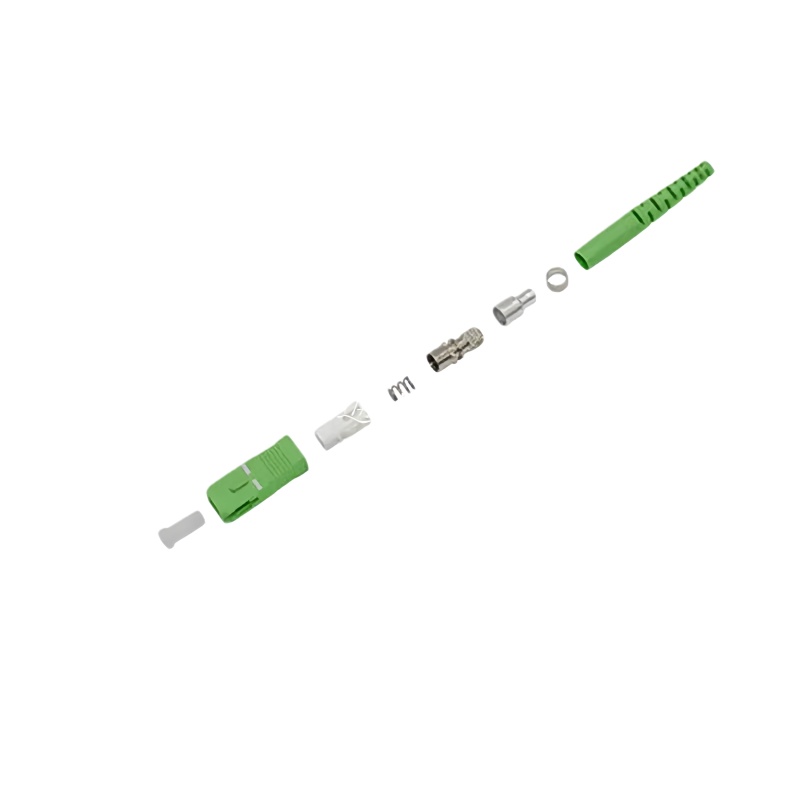
The SC (Subscriber Connector) was developed by Nippon Telegraph and Telephone (NTT) in the mid-1980s as a cost-effective, user-friendly alternative to the screw-on FC connector that dominated early fiber deployments. Its defining characteristics include a square, push-pull latching mechanism, a 2.5mm ceramic ferrule, and a molded plastic housing that has become instantly recognizable to fiber technicians worldwide.
The SC connector’s design addresses several practical concerns that plagued earlier connector types. The push-pull mechanism eliminates the need to rotate the connector body during mating—a significant advantage in dense patch panels where finger access is limited. The square housing provides positive orientation and prevents rotation, ensuring consistent alignment. And the audible “click” of the latch provides tactile confirmation that a proper connection has been made.
These features made the SC connector the dominant choice for telecommunications applications throughout the 1990s and early 2000s. Even today, with the proliferation of smaller-form-factor connectors like the LC, SC remains widely deployed in access networks, CATV systems, and test equipment where its robustness and reliability are valued over density.
The SC connector complies with the IEC 61754-4 standard, which defines the standard interface dimensions for the type SC family of connectors. This standardization ensures interoperability between components from different manufacturers and provides a baseline for performance expectations.
1.2 The “APC” Designation: What Does Angled Physical Contact Mean?
The “APC” designation refers to the polish applied to the ferrule end-face—specifically, an 8-degree angle relative to the perpendicular plane of the fiber axis. This seemingly simple geometric modification has profound implications for connector performance.
To understand why, we must first understand what happens when light encounters a fiber-to-fiber interface. In any connector, a small amount of light is reflected back toward the source due to the Fresnel reflection that occurs at the glass-air-glass interface. The magnitude of this reflection depends on the refractive index mismatch between the fiber core and the air gap (or index-matching material) between mated connectors.
In a PC (Physical Contact) or UPC (Ultra Physical Contact) connector, the ferrule end-face is polished perpendicular to the fiber axis. This means that any reflected light travels directly back down the fiber core toward the source—a phenomenon known as back-reflection. In an APC connector, the 8-degree angle ensures that reflected light is directed into the fiber cladding at an angle greater than the critical angle for total internal reflection. This reflected light is then rapidly attenuated as it propagates through the cladding, effectively eliminating it as a source of interference.
The APC connector was developed specifically to achieve extremely low back-reflection—less than -60 dB when the slanted angle is more than 8 degrees. This represents a reduction in reflected power of at least three orders of magnitude compared to a PC connector, and at least one order of magnitude compared to a UPC connector.
1.3 Physical Characteristics and Visual Identification
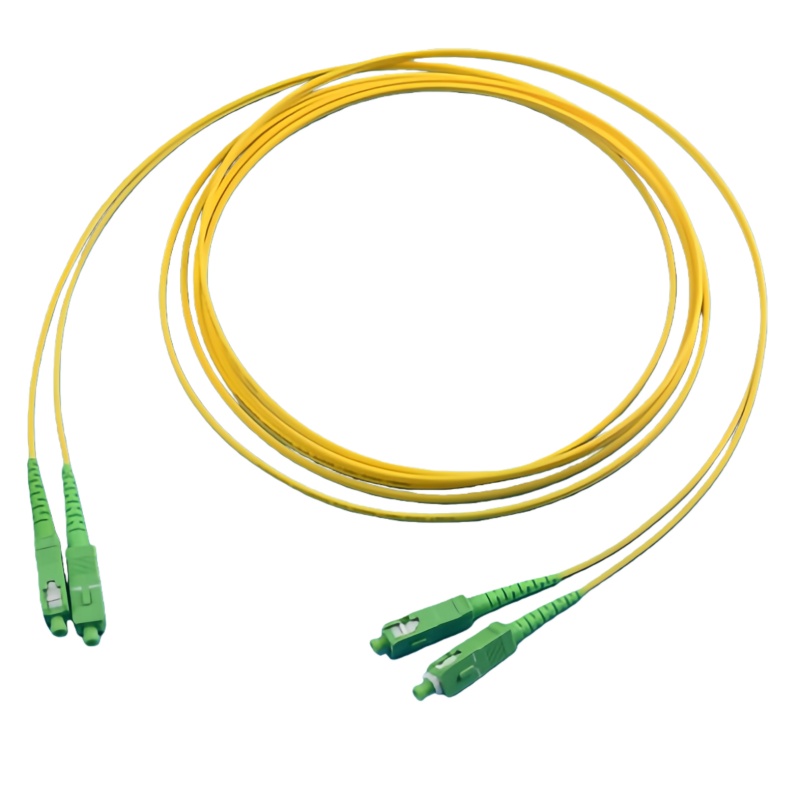
SC APC connectors are visually distinctive, which helps prevent costly mismating errors in the field. The industry has standardized on a green color code for the connector body and adapter housing to indicate APC polish. In contrast, UPC connectors are typically blue, while PC connectors (primarily for multimode applications) are often beige or black.
This color coding is not merely aesthetic—it serves a critical safety and performance function. Mating an APC connector with a UPC connector can damage the angled ferrule end-face, create excessive insertion loss, and generate high back-reflection that defeats the purpose of using APC in the first place. The green color provides an immediate visual cue that technicians can use to verify proper mating compatibility.
The ferrule itself is typically manufactured from zirconia ceramic, chosen for its hardness, dimensional stability, and thermal expansion characteristics that closely match those of the silica fiber it houses. High-precision manufacturing ensures that the fiber core is centered within the ferrule to within sub-micron tolerances, and that the 8-degree polish angle is maintained consistently across the entire end-face.
Part 2: The Physics of Performance — Why APC Matters
2.1 Return Loss: The Critical Parameter
Return loss is arguably the most important specification for connectors deployed in analog and high-precision networks. It quantifies the ratio of reflected optical power to incident optical power, expressed in decibels (dB). A higher return loss value indicates lower reflection—counterintuitively, a return loss of -60 dB means that only 0.0001% of incident power is reflected back toward the source.
Table 1: Comparison of Return Loss Specifications by Connector Polish Type
| Connector Polish Type | Typical Return Loss (dB) | Reflected Power (%) | Applications |
|---|---|---|---|
| PC (Physical Contact) | -30 to -40 | 0.1% to 0.01% | Legacy multimode, some single-mode |
| UPC (Ultra Physical Contact) | -40 to -55 | 0.01% to 0.0003% | Digital telecom, data centers |
| APC (Angled Physical Contact) | -60 to -70+ | 0.0001% to 0.00001% | Analog video, RFoF, test equipment, high-power |
Sources: Industry standards and manufacturer specifications
The difference between UPC and APC may appear small when expressed in decibels—perhaps -50 dB versus -65 dB. But the decibel scale is logarithmic, meaning that a 15 dB improvement represents a reduction in reflected power of approximately 97%. This is not a subtle difference; it’s a transformative one.
Industry standards provide clear guidance on minimum return loss requirements. The industry recommendation is that UPC connector return loss should be -50 dB or greater, while APC connector return loss should be -60 dB or greater. Premium APC connectors from manufacturers like Diamond achieve return loss above 70 dB for single-mode APC types, with insertion loss below 0.2 dB.
2.2 Insertion Loss: The Balance of Performance
While return loss is the headline specification for APC connectors, insertion loss—the amount of optical power lost through the connection—remains equally important for overall link budget considerations. APC connectors typically exhibit insertion loss in the range of 0.2 dB to 0.5 dB, with premium connectors achieving values below 0.2 dB.
The angled polish introduces a slight geometric inefficiency compared to perpendicular polishes, as the light path must refract slightly at the angled interface. This accounts for the marginally higher typical insertion loss of APC connectors compared to their UPC counterparts. However, for the vast majority of applications, this small additional loss is more than offset by the dramatic improvement in return loss.
Table 2: Typical SC APC Connector Specifications from Leading Manufacturers
| Parameter | Standard Grade | Premium/ULL Grade | Test Conditions |
|---|---|---|---|
| Insertion Loss (typical) | ≤ 0.3 dB | ≤ 0.2 dB | Per mated pair, 1310/1550 nm |
| Insertion Loss (maximum) | 0.5 dB | 0.34 dB | Per mated pair |
| Return Loss (minimum) | 55-60 dB | 65-70+ dB | Single-mode |
| Return Loss (typical) | 60-65 dB | 70+ dB | Single-mode |
| Durability | ≥ 500 cycles | ≥ 1000 cycles | Change < 0.2 dB |
| Operating Temperature | -40°C to +85°C | -40°C to +85°C | Per IEC 61753-1 |
Sources: Compilation of manufacturer datasheets and industry standards
2.3 The 8-Degree Angle: A Carefully Engineered Compromise
Why 8 degrees? This specific angle represents an optimization of competing requirements that fiber optic engineers have refined over decades.
If the angle were too shallow (less than approximately 6 degrees), the reflected light would not be sufficiently diverted into the cladding to ensure total internal reflection and rapid attenuation. Some light would still couple back into the fiber core, compromising return loss performance.
If the angle were too steep (greater than approximately 12 degrees), the insertion loss would increase significantly as the light path requires more dramatic refraction at the interface. Additionally, manufacturing tolerances become more challenging, and the risk of ferrule damage during mating increases.
The 8-degree standard emerged through extensive research and practical experience. At this angle, back-reflection is reduced to less than -60 dB—a level that effectively eliminates back-reflection as a concern for virtually all applications. Simultaneously, insertion loss remains well within acceptable limits for the vast majority of network designs.
The industry has converged around 8 degrees as the de facto standard for APC connectors. This standardization ensures interoperability between components from different manufacturers and simplifies the supply chain.
Part 3: SC APC in Analog Optical Networks
3.1 The Unique Challenges of Analog Transmission
Analog optical transmission differs fundamentally from its digital counterpart in ways that make connector performance—particularly return loss—critically important.
In a digital system, information is encoded as discrete ones and zeros. The receiver simply needs to distinguish between two states. As long as the signal-to-noise ratio exceeds a threshold, the receiver can recover the data perfectly. Moderate levels of reflection, noise, and distortion are tolerated because the digital decision threshold provides inherent noise immunity.
Analog systems have no such luxury. In an analog optical link—whether carrying cable television signals, radio frequency over fiber (RFoF), or precision sensor data—the information is encoded directly in the amplitude, phase, or frequency of the optical carrier. Any distortion introduced by the transmission medium directly corrupts the information content. There is no “error correction” in the digital sense; what arrives at the receiver is what you get.
This fundamental difference explains why analog networks are exquisitely sensitive to optical reflections. Reflected light traveling back toward the source can interact with the laser cavity, causing instability in the laser’s output wavelength and power. This phenomenon, known as optical feedback-induced noise, manifests as increased relative intensity noise (RIN) and degraded carrier-to-noise ratio (CNR).
Furthermore, multiple reflections along a fiber link can create multipath interference (MPI)—a form of signal distortion where delayed copies of the signal arrive at the receiver superimposed on the direct signal. In analog systems, MPI appears as ghost images in video, distortion in RF carriers, and degradation of composite second-order (CSO) and composite triple-beat (CTB) performance.
3.2 CATV and Broadband Distribution Networks
Cable television (CATV) networks represent one of the largest deployed bases of analog optical transmission systems in the world. Modern CATV architectures use a hybrid fiber-coaxial (HFC) topology, where optical fiber carries signals from the headend to neighborhood nodes, and coaxial cable completes the final distribution to subscribers.
The performance requirements for these networks are demanding. A typical CATV optical link must carry 77 to 110 channels of analog video (in NTSC or PAL formats), plus digital QAM carriers and DOCSIS data signals, all multiplexed onto a single optical wavelength—typically 1310 nm for shorter links or 1550 nm for longer spans using erbium-doped fiber amplifiers (EDFAs).
In these systems, CNR requirements are stringent. A typical specification requires CNR ≥ 50 dB for 77 NTSC channels with 0 dBm optical input power. CSO and CTB specifications are similarly demanding—typically ≥ 65 dB and ≥ 60 dB, respectively. Achieving these performance levels requires minimizing all sources of signal degradation, including connector reflections.
SC APC connectors are specified for the optical interfaces on CATV transmitters, optical nodes, and passive optical receivers. The SC/APC to RF analog signal interface is standard in FTTH CATV receivers, which convert optical signals to RF for coaxial distribution. These devices are passive in many cases—meaning they operate without electrical power, relying entirely on the optical signal itself—which makes optical efficiency and low reflection even more critical.
3.3 RF over Fiber (RFoF) Applications
RF over Fiber technology extends far beyond CATV. It enables the transport of radio frequency signals across distances and through environments where coaxial cable would introduce unacceptable loss or where electromagnetic interference would corrupt the signal.
Key RFoF applications include:
Satellite Communications: Transporting L-band signals from satellite dish antennas to indoor receiver equipment, eliminating the loss and frequency-dependent attenuation of long coaxial cable runs.
Distributed Antenna Systems (DAS): Carrying cellular and public safety radio signals from base station hotels to remote antenna units throughout large buildings, campuses, and tunnels.
Radar and Electronic Warfare: Distributing microwave signals in military systems where coaxial cable weight and loss are prohibitive.
Radio Astronomy and Scientific Instrumentation: Transporting extremely weak signals from antennas to processing equipment with minimal degradation.
In all these applications, the wide operating frequency range of typical RFoF links—often spanning from 45 MHz to 2400 MHz or higher—demands exceptional linearity and flatness. Reflections within the optical path can create frequency-dependent ripple in the link’s transfer function, degrading flatness and introducing distortion.
SC APC connectors have become the de facto standard for RFoF applications. Their low back-reflection protects laser stability, while the robust SC form factor provides reliable performance in field-deployed systems. Many RFoF transmitters and receivers are designed with SC/APC optical ports as standard equipment.
3.4 The Real-World Impact: A Case Study in CATV Performance
Consider a typical CATV optical link serving 500 subscribers through a single fiber. The link includes a transmitter at the headend, a 1×32 optical splitter in the field, and 32 optical nodes, each serving approximately 15 homes.
If this link were deployed with UPC connectors rather than APC, the cumulative effect of multiple reflections would manifest in several ways:
- Ghost Images: Viewers would see faint, shifted duplicates of the main image—particularly noticeable on channels with high-contrast content like text crawls or station logos.
- Degraded CNR: The carrier-to-noise ratio would drop by 1-3 dB, pushing marginal receivers below the threshold for acceptable picture quality and causing visible “snow” in analog channels.
- Increased Bit Error Rate: Digital QAM carriers would experience higher error rates, potentially causing pixelation, macroblocking, or complete loss of digital channels.
- Laser Instability: The transmitter laser would experience increased relative intensity noise, compounding the degradation across all channels.
These problems are notoriously difficult to diagnose and repair. They may appear intermittently, vary with temperature, or only manifest when specific channel lineups are in use. By specifying SC APC connectors from the outset, network designers eliminate a major source of these intractable performance issues.
Part 4: SC APC in High-Precision Optical Networks
4.1 Optical Test and Measurement Equipment
Perhaps no application demonstrates the importance of SC APC connectors more clearly than optical test and measurement. The instruments used to characterize fiber networks—OTDRs, optical loss test sets, optical spectrum analyzers, and return loss meters—must themselves exhibit return loss performance that exceeds the devices they are testing.
An OTDR measures the reflectance and attenuation of events along a fiber link by launching short optical pulses and analyzing the backscattered light. The instrument’s own connector ports can become sources of error if they generate excessive reflectance. A high-reflection connector at the OTDR port creates a large initial reflection that can saturate the instrument’s receiver, creating a “dead zone” near the instrument that obscures the first several meters to several hundred meters of fiber.
A properly connected APC connector pair will generate a reflective event with typically less than 0.5 dB loss and -55 dB to -65 dB reflectance. This low reflectance is essential for accurate OTDR measurements and for minimizing attenuation dead zones. Many OTDR manufacturers configure their instruments with APC ports specifically to minimize these near-end effects.
The angled single-mode test port on precision return loss meters guarantees highly accurate return loss measurements without requiring external termination for up to 50 dB return loss measurements. This capability is essential for characterizing components that themselves must meet stringent return loss specifications.
4.2 Interferometric Sensing and Metrology
Interferometry—the technique of extracting information from the interference pattern created when two light waves are superimposed—enables some of the most precise measurements known to science. Fiber optic interferometers are used for strain sensing, temperature monitoring, acoustic detection, and precision metrology in applications ranging from oil and gas exploration to structural health monitoring of bridges and buildings.
These systems are exquisitely sensitive to optical phase. Any unwanted reflection that couples back into the sensing fiber can create parasitic interference that corrupts the measurement signal. The high return loss of APC connectors—typically exceeding -65 dB—is essential for maintaining the phase purity required for interferometric applications.
Interferometric measurement systems themselves rely on high-quality connectors. The quality of the ferrule face has important influence on transmission parameters of optical connectors like attenuation and reflectance. Measurements of spherical height and apex offset for SC-APC connectors using interferometric techniques have demonstrated the critical relationship between ferrule geometry and connector performance.
4.3 High-Power Optical Systems
As optical power levels increase—in Raman amplifiers, high-power EDFAs, and industrial laser systems—connector performance takes on additional dimensions beyond simple optical specifications. High optical power can cause several failure mechanisms in fiber connectors:
Fiber End-Face Damage: Contamination on the connector end-face can absorb optical power and heat rapidly, causing localized melting or fracture of the glass surface.
Thermal Runaway: Poor physical contact between mated fibers creates an air gap that, under high optical power, can ionize and form a plasma that damages the fiber end-face.
Connector Body Heating: Even when the fiber itself remains intact, the connector body can absorb scattered light and heat to temperatures that exceed material ratings.
APC connectors offer inherent advantages for high-power applications. The angled end-face ensures that any light reflected at the interface is directed into the cladding rather than back toward the source, reducing the risk of laser damage from optical feedback. The physical contact design, when properly mated with clean end-faces, minimizes the air gap that can lead to thermal runaway.
Research has demonstrated that SP/APC connectors can withstand repeated connection and disconnection under high optical power—up to 22 dBm (approximately 160 mW)—without optical damage, provided the end-faces remain clean. However, for cleaning of connectors carrying optical power, reduction of power to a proper level not exceeding 15 dBm (approximately 32 mW) is recommended.
For even higher power applications, specially designed high-power SC connectors are available. These incorporate features such as expanded beam technology, improved thermal management, and specialized end-face treatments to withstand power levels far exceeding standard connector ratings.
4.4 Coherent Optical Communication Systems
Coherent optical communication—where information is encoded in both the amplitude and phase of the optical carrier—represents the cutting edge of high-capacity fiber transmission. Modern coherent systems operating at 400G, 800G, and emerging 1.6T data rates rely on advanced modulation formats such as DP-QPSK, DP-16QAM, and DP-64QAM.
These systems are extremely sensitive to phase noise. Any reflection that re-enters the laser cavity can perturb the laser’s phase, introducing phase noise that degrades the receiver’s ability to correctly demodulate the signal. The narrow-linewidth lasers used in coherent systems—often with linewidths below 100 kHz—are particularly susceptible to optical feedback.
While coherent systems are predominantly digital in their modulation, the underlying physics of phase-sensitive detection makes them behave more like analog systems when it comes to sensitivity to reflections. SC APC connectors, with their high return loss and stable performance, are essential for maintaining the phase stability that coherent systems require.
Part 5: SC APC vs. Alternatives — A Comparative Analysis
5.1 PC, UPC, and APC: The Polish Spectrum
The three primary connector polish types—PC, UPC, and APC—represent a spectrum of performance and cost trade-offs. Understanding these differences is essential for making informed connector selections.
PC (Physical Contact): The original connector polish design for single-mode fiber. The ferrule end-face is polished with a slight spherical curvature to ensure physical contact between fiber cores, eliminating the air gap that plagued early flat-polish connectors. PC connectors achieve return loss of -30 to -40 dB, adequate for many multimode applications and legacy single-mode systems. They are rarely specified for new single-mode deployments today.
UPC (Ultra Physical Contact): An evolution of PC polish achieved through more refined polishing techniques and tighter geometric tolerances. The improved surface quality and more precise radius of curvature enable return loss of -40 to -55 dB. UPC connectors have become the standard for digital telecommunications and data center applications, where their lower cost and slightly better insertion loss (compared to APC) are valued.
APC (Angled Physical Contact): The gold standard for applications requiring minimal back-reflection. The 8-degree angled polish ensures that reflected light is directed into the cladding rather than back toward the source, achieving return loss of -60 dB or better. APC connectors are essential for analog video, RFoF, high-power systems, and precision test equipment.
The UPC connector has a lower back reflection and better optical return loss (-50dB or higher) than the PC connector. However, APC connectors have an 8° angle end face that dramatically improves return loss performance.
5.2 SC vs. LC vs. FC: Form Factor Considerations
While polish type is the primary determinant of return loss performance, the connector form factor also influences practical deployment considerations.
SC (Subscriber Connector): The SC connector offers a push-pull latching mechanism, a robust 2.5mm ferrule, and excellent durability—typically rated for 500 to 1000 mating cycles. Its relatively large size compared to newer form factors is offset by its reliability and ease of use. The SC connector remains the preferred choice for access networks, test equipment, and applications where frequent mating is expected.
LC (Lucent Connector): The LC connector uses a 1.25mm ferrule—half the diameter of the SC ferrule—enabling approximately twice the port density in patch panels and transceivers. LC has become the dominant connector in data centers and high-density telecommunications equipment. LC APC connectors are available and offer the same return loss performance as SC APC, but their smaller ferrule can be more challenging to clean and inspect.
FC (Ferrule Connector): The FC connector uses a threaded coupling mechanism that provides a secure, vibration-resistant connection. It was widely deployed in telecommunications before the SC connector’s introduction and remains common in test equipment and some high-vibration industrial applications. FC APC connectors offer excellent performance but are less convenient for frequent mating and unmating.
The choice between SC APC and LC APC often comes down to density requirements versus ease of handling. For field-deployed equipment, test ports, and applications where technicians will frequently connect and disconnect fibers, the larger SC form factor offers practical advantages. For high-density patch panels and transceiver interfaces, LC APC is the logical choice.
5.3 When APC Is Non-Negotiable
While connector selection always involves trade-offs, certain applications categorically require APC polish:
- Analog Video Distribution (CATV): Any connector in the optical path between the headend transmitter and the optical node should be APC to prevent reflections from degrading picture quality.
- RF over Fiber Links: The wide bandwidth and stringent linearity requirements of RFoF systems demand the high return loss that only APC can provide.
- High-Power Optical Systems: Applications exceeding approximately 100 mW (20 dBm) of optical power should use APC connectors to minimize the risk of connector damage from optical feedback and thermal effects.
- Optical Test Equipment Ports: OTDRs, optical loss test sets, and return loss meters should be equipped with APC ports to ensure measurement accuracy.
- DWDM and Coherent Systems: While UPC may be acceptable in some digital links, the phase sensitivity of coherent systems and the narrow channel spacing of DWDM favor APC for all connections that will be mated and unmated in the field.
Part 6: Installation, Maintenance, and Troubleshooting
6.1 Critical Importance of Connector Cleanliness
The exceptional return loss performance of SC APC connectors is entirely dependent on a clean, undamaged end-face. Research has shown that contamination on the core of an APC connector can dramatically degrade return loss—by an average of 14.2 dB. A connector that would otherwise achieve -65 dB return loss may measure only -50 dB when contaminated—effectively reducing its performance to UPC levels.
This sensitivity to contamination has practical implications for field operations. Technicians must:
- Inspect every connector before mating, using a fiber microscope with appropriate magnification (typically 200x to 400x) to evaluate end-face condition.
- Clean connectors using proper tools and techniques, including dry cleaning with specialized wipes or click-cleaners, followed by wet cleaning with optical-grade solvent when necessary.
- Re-inspect after cleaning to verify that contamination has been removed and that no new scratches or defects have been introduced.
- Use dust caps religiously on unmated connectors and adapters to prevent contamination ingress.
For connectors that carry optical power, special precautions apply. Reduction of power to a proper level not exceeding 15 dBm is recommended before cleaning to avoid the risk of thermal damage. Cleaned connectors should be inspected and coupled only if the end faces meet the cleaning requirements.
6.2 Proper Mating and Demating Techniques
SC connectors are designed for straight insertion and withdrawal—no rotation is required or desired. The push-pull mechanism should be operated by grasping the connector body, not the fiber cable, to avoid stressing the fiber or the connector-cable interface.
When mating SC APC connectors:
- Align the connector key with the adapter slot.
- Push straight in until the latch clicks audibly.
- Verify that the connector is fully seated by gently pulling back on the connector body (not the cable).
When demating:
- Grasp the connector body firmly.
- Pull straight back—do not wiggle or twist.
- Immediately install dust caps on both the connector and the adapter port.
APC connectors should never be mated with UPC connectors. The angle mismatch will prevent proper physical contact, resulting in high insertion loss (typically > 3 dB) and high back-reflection. Worse, the angled ferrule of the APC connector can be damaged by contact with the flat ferrule of the UPC connector.
6.3 Troubleshooting Common Issues
When an SC APC connection exhibits poor performance, systematic troubleshooting can identify the root cause:
High Insertion Loss: Check for contamination on the end-face, improper seating in the adapter, or damage to the ferrule. Also verify that the mating connector is also APC polish—mismatched polish types will cause high loss.
Low Return Loss (High Reflectance): Contamination is the most common cause. Inspect and clean both connectors. If the problem persists, check for scratches or pits on the ferrule end-face, particularly in the core region.
Intermittent Performance: Look for loose adapters, damaged latches, or fiber stress that causes the ferrule to shift within the connector body. Temperature cycling can also cause intermittent issues if the connector’s thermal expansion characteristics are poorly matched.
Complete Signal Loss: Verify that the fiber is not broken and that the connectors are properly mated. Check for macrobends in the fiber near the connector that might be exceeding the fiber’s bend radius specification.
Part 7: Market Landscape and Industry Trends
7.1 Global Market Size and Growth Projections
The global fiber optic connector market continues to expand, driven by increasing bandwidth demand, 5G network deployments, data center construction, and fiber-to-the-home initiatives worldwide.
Table 3: Global Fiber Optic Connector Market Size and Growth Projections
| Metric | Value | Source |
|---|---|---|
| 2025 Market Size | $5.61 billion | GII Research |
| 2026 Market Size (Projected) | $5.98 billion | GII Research |
| 2026 Market Size (Alt. Estimate) | $2.90 billion | Global Market Statistics |
| CAGR (2025-2026) | 6.5% | GII Research |
| 2035 Projection | $3.06-3.58 billion | Various estimates |
| SC Connector Segment (2024) | $903 million | QY Research |
| SC Connector Segment (2031 Projection) | $1.04 billion | QY Research |
Sources: Multiple market research reports
The SC connector segment alone was estimated to be worth approximately $903 million in 2024 and is forecast to grow to $1.04 billion by 2031, representing a CAGR of 2.1%. While this growth rate is modest compared to the overall connector market, it reflects the maturity of the SC form factor and its established position in key applications.
The broader commercial telecom fiber optic connector market shows stronger growth, with projections reaching $7.8 billion by 2032.
7.2 Regional Market Dynamics
The fiber optic connector market exhibits distinct regional characteristics:
Asia Pacific: Dominates the global market in both production and consumption. China’s extensive FTTH deployments and 5G network build-out drive demand for SC APC connectors in access networks. The region also houses the majority of connector manufacturing capacity.
North America: Strong growth driven by data center interconnect, CATV network upgrades, and broadband expansion programs. The United States remains a key market for high-performance SC APC connectors in CATV and RFoF applications.
Europe: Mature market with steady replacement demand and growth in specialized applications including industrial automation, medical imaging, and scientific instrumentation.
Emerging Markets: Rapidly expanding fiber infrastructure in India, Southeast Asia, Africa, and Latin America creates new demand for cost-effective connector solutions, though premium APC connectors may be limited to higher-value applications.
7.3 Competitive Landscape
The SC APC connector market includes both major multinational manufacturers and specialized component suppliers. Key players include:
- CommScope: Offers a comprehensive range of SC APC connectors and adapters, with products meeting IEC 61753-1 environmental standards and achieving return loss minimum of 65 dB.
- Diamond: Known for premium connectors using Active Core Alignment (ACA) technology and composite ferrules, achieving return loss above 70 dB for single-mode APC types.
- Amphenol: Provides SC connectors with typical insertion loss of 0.23 dB for APC and return loss greater than 65 dB.
- Corning: Offers high-precision mechanical splice connectors and factory-polished SC APC assemblies with typical insertion loss of 0.3 dB.
- Siemon: Supplies SC APC cable assemblies for high-speed telecommunication network fiber applications including FTXX, PON, POL, CATV, LAN, and WAN.
The market also includes numerous regional manufacturers, particularly in China, offering cost-competitive products for price-sensitive applications.
7.4 Technology Trends
Several trends are shaping the evolution of SC APC connectors:
Ultra-Low Loss (ULL) Connectors: Premium connectors achieving insertion loss below 0.2 dB and return loss above 70 dB are increasingly specified for long-haul and high-performance applications where every fraction of a decibel matters.
High-Power Variants: As optical power levels continue to increase in Raman amplifiers and industrial applications, specialized high-power SC APC connectors with enhanced thermal management and damage resistance are gaining adoption.
Field-Installable Connectors: Pre-polished field-installable SC APC connectors enable rapid deployment without the need for fusion splicing or epoxy curing, reducing installation time and cost in FTTH and enterprise applications.
Automated Manufacturing: Advances in automated polishing, inspection, and testing are improving consistency and reducing cost, making premium APC performance more accessible.
Part 8: The Future of SC APC Technology
8.1 Evolving Standards and Requirements
The standards landscape for fiber optic connectors continues to evolve. Key developments include:
IEC 61754 Series: The ongoing maintenance and expansion of the IEC 61754 standard series ensures that SC connector interface dimensions remain clearly defined and interoperable. The latest revision, IEC 61754-4:2013, defines the standard interface dimensions for the type SC family of connectors.
IEC 61300 Series: Test and measurement standards continue to be refined to provide more accurate characterization of APC connector performance, including wavelength dependence of attenuation and return loss.
High-Power Standards: As high-power applications proliferate, new standards and recommended practices for high-power connector qualification and safe handling are emerging.
8.2 Integration with Next-Generation Networks
SC APC connectors will continue to play essential roles in several key application areas:
5G Fronthaul: The dense fiber infrastructure required for 5G radio access networks creates demand for reliable, field-proven connectors. SC APC is well-suited for the eCPRI and CPRI interfaces that connect remote radio heads to baseband units.
Fiber Deep Architectures: CATV operators are pushing fiber deeper into their networks, reducing the size of coaxial serving areas and improving performance. Each new fiber node creates additional demand for SC APC connectors.
Quantum Communications: Emerging quantum key distribution (QKD) networks are extremely sensitive to optical loss and reflections. APC connectors are essential for maintaining the single-photon-level signals that QKD requires.
Coherent PON: Next-generation passive optical networks are adopting coherent detection techniques to achieve higher speeds and longer reaches. These coherent systems share the phase sensitivity that makes APC connectors critical.
8.3 Sustainability and Lifecycle Considerations
The fiber optic industry is increasingly focused on sustainability. Connector manufacturers are addressing environmental concerns through:
- Reduced packaging waste and increased use of recycled materials
- Extended product lifetimes through improved durability and field-repairable designs
- Energy-efficient manufacturing processes that reduce carbon footprint
SC APC connectors, with their proven reliability and long service life (often exceeding 30 years), align well with sustainability objectives. Their continued use in infrastructure applications avoids the environmental impact of premature replacement.
Frequently Asked Questions
Q1: What is the fundamental difference between UPC and APC connectors, and why does it matter?
The fundamental difference is the polish angle on the ferrule end-face. UPC connectors have a perpendicular polish (0-degree angle), while APC connectors have an 8-degree angled polish. This angle change has a dramatic effect: in UPC, reflected light travels straight back toward the source, potentially causing laser instability and signal interference. In APC, the angle directs reflected light into the fiber cladding where it is rapidly attenuated. This reduces back-reflection from approximately -50 dB (UPC) to -60 dB or better (APC)—a reduction in reflected power of at least 90%. For analog signals (like CATV) and precision measurement equipment, this difference is the line between acceptable performance and failure.
Q2: Why are SC APC connectors colored green?
The green color is an industry-standard visual identifier for APC polish. This color coding serves a critical safety and performance function: mating an APC connector with a UPC connector (typically blue) can damage the angled ferrule end-face, create excessive insertion loss, and generate high back-reflection that defeats the purpose of using APC. The green color provides an immediate visual cue that technicians can use to verify proper mating compatibility, preventing costly mistakes in the field.
Q3: Can I mate an SC APC connector with an SC UPC connector?
No. Mating an APC connector with a UPC connector is strongly discouraged and will result in several problems. First, the angled ferrule of the APC connector will not make proper physical contact with the flat ferrule of the UPC connector, resulting in high insertion loss (typically > 3 dB). Second, the mismatch will generate very high back-reflection—potentially worse than using a PC connector. Third, the angled ferrule can be physically damaged by contact with the flat ferrule, permanently degrading the APC connector’s performance. Always mate APC with APC and UPC with UPC.
Q4: What are the typical return loss and insertion loss specifications for SC APC connectors?
Typical specifications vary by grade. Standard-grade SC APC connectors achieve insertion loss of 0.2-0.3 dB and return loss of 60-65 dB. Premium ultra-low-loss (ULL) connectors achieve insertion loss below 0.2 dB and return loss above 70 dB. Maximum specifications are typically 0.5 dB insertion loss and 55-60 dB return loss. For high-performance analog and measurement applications, premium connectors with return loss ≥ 65 dB are recommended.
Q5: How does contamination affect SC APC connector performance?
Contamination is the single most common cause of poor connector performance. Research has shown that contamination on the core of an APC connector degrades return loss by an average of 14.2 dB. A connector that would achieve -65 dB return loss when clean may measure only -50 dB when contaminated—effectively reducing its performance to UPC levels. Always inspect connectors with a fiber microscope before mating, clean using appropriate tools and techniques, and re-inspect after cleaning.
Q6: What applications absolutely require APC connectors?
Several applications categorically require APC polish: (1) Analog video distribution (CATV)—any connector in the optical path should be APC to prevent reflections from degrading picture quality; (2) RF over Fiber links—the wide bandwidth and stringent linearity requirements demand APC; (3) High-power optical systems (> 20 dBm)—APC minimizes the risk of connector damage from optical feedback; (4) Optical test equipment ports—OTDRs and return loss meters need APC ports for measurement accuracy; (5) Coherent optical systems—phase-sensitive coherent detection favors APC.
Q7: How do SC APC connectors perform in high-power applications?
SC APC connectors can operate safely at power levels up to approximately 22 dBm (160 mW) with clean end-faces. However, when cleaning connectors that carry optical power, power should be reduced to no more than 15 dBm (32 mW) to avoid thermal damage during the cleaning process. For higher power applications, specialized high-power SC connectors with enhanced thermal management and damage resistance are available.
Q8: How do I properly test an SC APC connector installation?
Proper testing requires attention to the connector’s APC characteristics. When using an OTDR, a properly connected APC connector pair will generate a reflective event with typically less than 0.5 dB loss and -55 dB to -65 dB reflectance. Use a launch fiber with an APC connector to overcome the OTDR’s dead zone. For insertion loss testing, use a light source and power meter with appropriate APC reference cables. For return loss verification, use a dedicated return loss meter configured with an APC test port.
Q9: What is the lifespan and durability of SC APC connectors?
SC APC connectors are typically rated for 500 to 1000 mating cycles with insertion loss change of less than 0.2 dB. Premium connectors may achieve 1000 or more cycles. The expected service life of properly maintained SC APC connectors in infrastructure applications can exceed 30 years. Environmental factors—temperature cycling, humidity, vibration—will affect actual lifespan.
Q10: How do SC APC connectors compare to LC APC connectors?
Both offer equivalent optical performance—return loss of 60-70+ dB and insertion loss of 0.2-0.5 dB. The primary differences are mechanical: SC uses a 2.5mm ferrule with a push-pull latch, while LC uses a 1.25mm ferrule with a latch mechanism similar to RJ-45 connectors. SC is larger and easier to handle in field applications; LC enables higher density in patch panels. The choice between them depends on application requirements: SC is preferred for test equipment and field-deployed equipment; LC dominates in high-density data center applications.
Conclusion: The Enduring Value of SC APC
In an industry that celebrates the latest innovations—400G coherent optics, hollow-core fiber, quantum key distribution—it might seem unusual to devote extensive attention to a connector technology that has been with us for decades. Yet the SC APC connector exemplifies a truth that experienced engineers understand well: the fundamentals matter, and they matter most when precision is paramount.
The 8-degree angled polish that defines APC technology solves a fundamental physical problem—Fresnel reflection at glass-air interfaces—with elegant simplicity. By redirecting reflected light into the cladding, APC connectors eliminate a source of noise and instability that would otherwise corrupt analog signals, destabilize lasers, and compromise measurement accuracy. The SC form factor, with its robust push-pull mechanism and 2.5mm ferrule, provides the mechanical reliability that field applications demand.
For CATV engineers striving to deliver pristine video to millions of subscribers, for RFoF system designers extending microwave signals across challenging environments, for test equipment manufacturers building the instruments that characterize our fiber infrastructure, for researchers pushing the boundaries of interferometric sensing—for all these professionals and many more—the SC APC connector is not merely one option among many. It is the essential choice.
As fiber networks continue their inexorable expansion into every corner of our connected world, the demand for precision, reliability, and signal integrity will only grow. The SC APC connector, proven across billions of connections and refined through decades of manufacturing innovation, stands ready to meet that demand. It is, and will remain, a critical enabler of the high-performance optical networks that power our digital future.