
IEC 61300-3-25 gives a defined way to measure concentricity for non-angled ferrules, but that result answers only one part of connector quality. Bore geometry affects fibre position, the installed fibre adds its own offset, polishing controls the contact surface, and assembly conditions affect the finished connection. A ferrule report therefore cannot replace optical and end-face tests on the completed connector.
Buyers often request one concentricity number and assume it predicts connector loss. That shortcut ignores whether the report covers the bare bore or an installed fibre, and it overlooks fibre diameter tolerance, adhesive distribution, ferrule outside geometry, angular bore error, spring force, polishing and the reference connector used during optical test. A better specification identifies the measurement state, controls the ferrule as a component and verifies the terminated assembly as a separate product.
Scope boundary: IEC 61300-3-25 applies to non-angled ferrules. An APC assembly adds angle, key-orientation and end-face-geometry controls, so a buyer should not present a non-angled concentricity report as complete APC approval evidence.
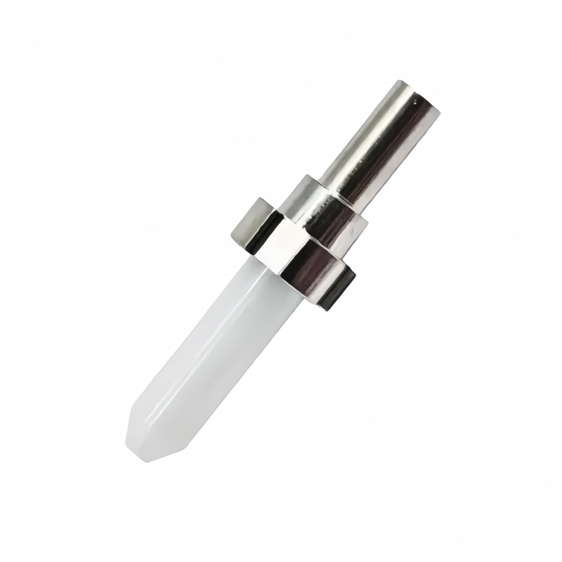
Which Ferrule Dimensions Matter to Assembly Quality?
Each dimension has a different function. Ask the supplier to identify the measurement method and sampling rule rather than submitting an unlabeled inspection screenshot.
| Merkmal | Warum das wichtig ist | Common misunderstanding | Erforderliche Nachweise |
|---|---|---|---|
| Bore diameter and form | Controls fibre fit and adhesive space through the ferrule | One diameter value describes the full bore | Measurement locations, method and lot summary |
| Bore-to-outer-diameter concentricity | Influences where the fibre sits relative to the ferrule axis | A good component value guarantees low connector loss | Component report plus completed-assembly optical result |
| Ferrule outer geometry | Works with the adapter sleeve to align the mating pair | Only the bore affects alignment | Dimensional drawing and gauge traceability |
| End-face geometry after polish | Controls physical contact and stress at the fibre interface | The ferrule supplier owns the final end face | Finished-connector geometry and visual records |
| Material and surface condition | Affects wear, polishing behaviour and defect risk | All white ceramic ferrules are interchangeable | Material declaration, approved source and change notice |
How Should Ferrule Data Be Used During Supplier Approval?
Use ferrule measurements to control the incoming component and finished optical data to release the connector. Keeping those decisions separate makes a failure easier to locate.
Approve the measurement definition
A tolerance without a method invites incomparable data. Record the gauge type, calibration route, measurement positions and whether reported values are individual readings, averages or process summaries.
Link lots across the process
The connector record should link ferrule lot, fibre lot, adhesive batch, polishing batch and final test. When loss shifts, that trace lets engineering test a cause instead of blaming every ceramic component in stock.
Inspect after polishing and cleaning
A dimensionally acceptable ferrule can still carry debris, scratches, pits or a damaged fibre. End-face inspection belongs after the final cleaning stage, and the record should identify the connector rather than only the production line.
Use reference artefacts consistently
Optical results move when the reference connector, adapter or cleaning condition changes. State how reference items are qualified, stored and replaced so supplier and buyer measurements remain comparable.
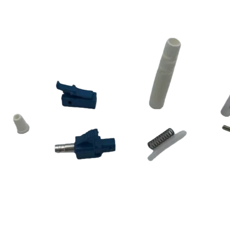
Failure Analysis: Component Defect or Assembly Defect?
Use evidence from both levels before issuing a supplier corrective action. The table keeps the investigation from stopping at the first plausible cause.
| Symptom | Component checks | Assembly checks | Disposition |
|---|---|---|---|
| High or unstable loss | Bore and outer-geometry data by ferrule lot | Fibre position, polish, contamination and reference setup | Quarantine the linked lots and repeat with controlled references |
| Visible core offset | Concentricity and bore-form trace | Adhesive cure and fibre seating process | Cross-section samples before assigning root cause |
| Scratches or pits | Incoming ferrule surface condition | Polishing film, cleaning and handling | Separate incoming damage from process damage |
| Good initial result, poor remate | Outer geometry and material consistency | Adapter sleeve, spring force and end-face cleanliness | Run controlled remating and inspect between stages |
| Lot-to-lot shift | Supplier material and tooling change | Fixture, operator and reference-cord change | Review both change logs against the first failing lot |
Standards und Belege zur Untermauerung der Bestellung
IEC 61300-3-25:2016 defines procedures for bore-to-ferrule-axis concentricity on bare non-angled ferrules and fibre-core-to-ferrule-axis concentricity after fibre installation. The IEC catalogue lists the third edition as valid with a stability date of 2034.
Bore concentricity and bore angle are separate characteristics. IEC 61300-3-54:2019 addresses angular misalignment between a cylindrical ferrule bore axis and the outside-diameter datum axis.
Die Ausgabe 2022 befasst sich mit Verunreinigungen, Kratzern und Mängeln an den Stirnflächen und stellt fest, dass eine Sichtprüfung die optische Qualifizierung nicht ersetzt. Siehe Prüfung von Steckverbindern gemäß IEC 61300-3-35.
Corning erklärt, dass GR-326 eine Leistungsspezifikation für fertige Singlemode-Stecker- und Jumper-Baugruppen ist und keine Angabe zu einzelnen Komponenten darstellt. Siehe Anwendungshinweis von Corning zu GR-326.
Laboratory Acceptance Note
A ferrule purchase should include dimensional evidence, lot traceability and change control. A connector purchase should additionally include end-face and optical evidence from the completed assembly. Keeping both records provides a defensible path from raw component to link performance.
- Define each ferrule characteristic and its measurement method
- Identify the sampling plan and lot boundaries
- Link ferrule lots to completed connector serials or batches
- Inspect and test after final polishing and cleaning
- Retain reference artefact and calibration records with the report
Für ein projektspezifisches Angebot sehen Sie sich bitte das Angebot von Fenxi an FC-Steckverbinderkomponenten, LC-Steckverbinder-Sortiment, SC-Steckerkomponenten, und Leitfaden zu den Materialien für Steckverbinderhülsen. Bitte geben Sie den Zielmarkt, die Anschlussschnittstellen, den Fasertyp, den Kabelaufbau, die Stückzahlen, die Zeichnungsversion und die erforderlichen Prüfprotokolle an. In der Antwort werden dann die Standardoptionen aus dem Katalog von den Artikeln unterschieden, die einer Bestätigung bedürfen oder für die Sonderwerkzeuge erforderlich sind.