
IEC 61300-3-25 gives a defined way to measure concentricity for non-angled ferrules, but that result answers only one part of connector quality. Bore geometry affects fibre position, the installed fibre adds its own offset, polishing controls the contact surface, and assembly conditions affect the finished connection. A ferrule report therefore cannot replace optical and end-face tests on the completed connector.
Buyers often request one concentricity number and assume it predicts connector loss. That shortcut ignores whether the report covers the bare bore or an installed fibre, and it overlooks fibre diameter tolerance, adhesive distribution, ferrule outside geometry, angular bore error, spring force, polishing and the reference connector used during optical test. A better specification identifies the measurement state, controls the ferrule as a component and verifies the terminated assembly as a separate product.
Scope boundary: IEC 61300-3-25 applies to non-angled ferrules. An APC assembly adds angle, key-orientation and end-face-geometry controls, so a buyer should not present a non-angled concentricity report as complete APC approval evidence.
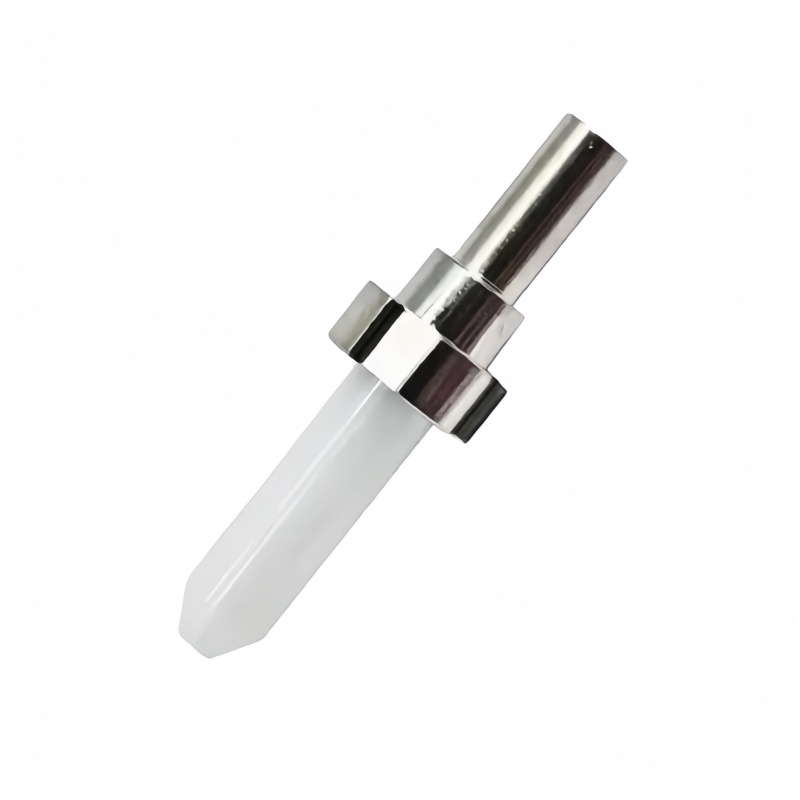
Which Ferrule Dimensions Matter to Assembly Quality?
Each dimension has a different function. Ask the supplier to identify the measurement method and sampling rule rather than submitting an unlabeled inspection screenshot.
| Característica | Por qué es importante | Common misunderstanding | Required evidence |
|---|---|---|---|
| Bore diameter and form | Controls fibre fit and adhesive space through the ferrule | One diameter value describes the full bore | Measurement locations, method and lot summary |
| Bore-to-outer-diameter concentricity | Influences where the fibre sits relative to the ferrule axis | A good component value guarantees low connector loss | Component report plus completed-assembly optical result |
| Ferrule outer geometry | Works with the adapter sleeve to align the mating pair | Only the bore affects alignment | Dimensional drawing and gauge traceability |
| End-face geometry after polish | Controls physical contact and stress at the fibre interface | The ferrule supplier owns the final end face | Finished-connector geometry and visual records |
| Material and surface condition | Affects wear, polishing behaviour and defect risk | All white ceramic ferrules are interchangeable | Material declaration, approved source and change notice |
How Should Ferrule Data Be Used During Supplier Approval?
Use ferrule measurements to control the incoming component and finished optical data to release the connector. Keeping those decisions separate makes a failure easier to locate.
Approve the measurement definition
A tolerance without a method invites incomparable data. Record the gauge type, calibration route, measurement positions and whether reported values are individual readings, averages or process summaries.
Link lots across the process
The connector record should link ferrule lot, fibre lot, adhesive batch, polishing batch and final test. When loss shifts, that trace lets engineering test a cause instead of blaming every ceramic component in stock.
Inspect after polishing and cleaning
A dimensionally acceptable ferrule can still carry debris, scratches, pits or a damaged fibre. End-face inspection belongs after the final cleaning stage, and the record should identify the connector rather than only the production line.
Use reference artefacts consistently
Optical results move when the reference connector, adapter or cleaning condition changes. State how reference items are qualified, stored and replaced so supplier and buyer measurements remain comparable.
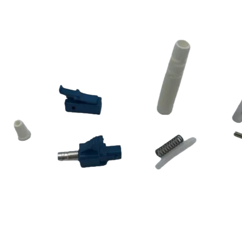
Failure Analysis: Component Defect or Assembly Defect?
Use evidence from both levels before issuing a supplier corrective action. The table keeps the investigation from stopping at the first plausible cause.
| Síntoma | Component checks | Assembly checks | Disposition |
|---|---|---|---|
| High or unstable loss | Bore and outer-geometry data by ferrule lot | Fibre position, polish, contamination and reference setup | Quarantine the linked lots and repeat with controlled references |
| Visible core offset | Concentricity and bore-form trace | Adhesive cure and fibre seating process | Cross-section samples before assigning root cause |
| Scratches or pits | Incoming ferrule surface condition | Polishing film, cleaning and handling | Separate incoming damage from process damage |
| Good initial result, poor remate | Outer geometry and material consistency | Adapter sleeve, spring force and end-face cleanliness | Run controlled remating and inspect between stages |
| Lot-to-lot shift | Supplier material and tooling change | Fixture, operator and reference-cord change | Review both change logs against the first failing lot |
Normas y pruebas que respaldan la orden de compra
IEC 61300-3-25:2016 defines procedures for bore-to-ferrule-axis concentricity on bare non-angled ferrules and fibre-core-to-ferrule-axis concentricity after fibre installation. The IEC catalogue lists the third edition as valid with a stability date of 2034.
Bore concentricity and bore angle are separate characteristics. IEC 61300-3-54:2019 addresses angular misalignment between a cylindrical ferrule bore axis and the outside-diameter datum axis.
La edición de 2022 aborda los residuos, rayones y defectos en las caras finales, y establece que la inspección visual no sustituye a la calificación óptica. Véase Inspección de conectores según la norma IEC 61300-3-35.
Corning explains that GR-326 is a performance specification for completed single-mode connector and jumper assemblies, not an isolated component claim. See Corning application note on GR-326.
Laboratory Acceptance Note
A ferrule purchase should include dimensional evidence, lot traceability and change control. A connector purchase should additionally include end-face and optical evidence from the completed assembly. Keeping both records provides a defensible path from raw component to link performance.
- Define each ferrule characteristic and its measurement method
- Identify the sampling plan and lot boundaries
- Link ferrule lots to completed connector serials or batches
- Inspect and test after final polishing and cleaning
- Retain reference artefact and calibration records with the report
Para obtener una cotización específica para tu proyecto, consulta la página de Fenxi FC connector components, Gama de conectores LC, SC connector components, y connector ferrule material guide. Envía el mercado de destino, las interfaces de conexión, el tipo de fibra, la estructura del cable, las cantidades, la revisión del plano y los registros de pruebas requeridos. De esta manera, la respuesta podrá distinguir entre las opciones estándar del catálogo y los artículos que requieran confirmación o herramientas personalizadas.