
A receiver that is fed too much light fails in the same way as one that is fed too little: the bit error rate climbs and the link becomes unreliable. Long spans remove enough power on their own, but on short spans, in PON head-ends and on test benches the signal arrives above the receiver overload point. An attenuator removes a known number of decibels, and the three decisions that go wrong most often are the dB value, the form factor and the polish.
Why an Otherwise Healthy Link Needs Attenuation
Every optical receiver has a working window. At the bottom sits sensitivity, the weakest signal it can still recover; at the top sits the overload point, the strongest it can accept before the photodiode saturates and the waveform distorts. A transmitter rated for 40 km or 80 km is built to overcome a large loss budget, so it launches several decibels more power than a short-reach module. Drop that transmitter onto a 300 m run and almost none of the budget is consumed: the light arrives hot and the link tests badly even though nothing is damaged or dirty.
The same arithmetic appears in four other places: an OLT port feeding a short feeder run in a PON, channel power that has to be levelled before a DWDM multiplexer, an analogue video link with a distorted carrier, and a commissioning bench where a defined amount of loss has to simulate a span that does not exist yet. All of them are one problem — too much light in the wrong place.
Fixed, Variable or Inline: Three Different Jobs
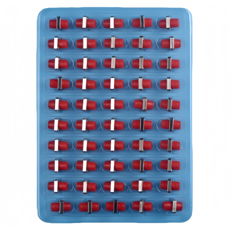
The first fork is whether the attenuation value is set at the factory or adjusted in the field. A fixed attenuator holds one value with no moving parts, which makes it stable, repeatable and inexpensive — the right choice wherever the loss budget is signed off. A variable optical attenuator can be dialled or clicked across a range, and belongs in commissioning or anywhere the correct figure has to be found by measurement. Ordering a variable unit for a permanent install pays for a mechanism nobody will touch.
There is also a mechanical difference that decides power handling. Attenuators built on metal-ion doped fiber absorb the light inside a short fiber length, which keeps wavelength dependence low and tolerates a few hundred milliwatts. Cheaper units that create a controlled air gap or a coated mirror scatter and reflect instead, raising wavelength dependence and usually limiting input to about 10 mW. For a receive path either type works; in front of an amplifier only the doped-fiber type is safe. A matched set is listed under faseroptisches zubehör.
| Typ | Attenuation | Best used for | Watch out for |
|---|---|---|---|
| Fixed plug-in | One factory value, 1–30 dB in 1 dB steps | Production links, receiver protection, permanent balancing | Value cannot be changed if the design shifts |
| Stepwise variable | Click stops, often 0–30 dB | Commissioning, field trials, re-balancing | Moving parts; repeatability quoted per setting |
| Continuously variable | Dial-adjustable, 0–30 dB | Lab work, power levelling, live tuning | Higher insertion loss at the minimum setting |
| Inline (cabled) | Fixed value built into a short cable assembly | Crowded panels where a rigid plug body will not fit | Extra cable to manage and store |
Working Out the dB Value Before You Order
Picking the value is subtraction, not guesswork. Take the power that actually arrives at the receiver, subtract the maximum input it can accept, and the difference is the excess to remove. Round up to the nearest increment, then check that the result still leaves the signal above sensitivity. The same arithmetic runs in the opposite direction in the loss budget published by the Fiber Optic Association.
Three points keep the answer honest. Measure the received power instead of trusting the data sheet, because a short span performs better than the budget predicts. Allow for the attenuator’s own insertion loss. And leave one or two decibels of margin, because a part chosen to sit exactly at the overload limit drifts out of range the first time a cord is re-terminated.
| Scenario | Received power | Receiver max input | Excess to remove | Part to order |
|---|---|---|---|---|
| 40 km optics on a 300 m span | −1 dBm | −8 dBm | 7 dB | 8 dB |
| OLT port above a class B+ ONU | +2 dBm | −8 dBm | 10 dB | 10 or 11 dB |
| DWDM channel balancing | +3 dBm | Not critical | Match the weakest channel | 1–5 dB per channel |
| Bench simulation of a 20 km span | +3 dBm | −20 dBm | 23 dB | Variable, 0–30 dB |
Form Factor: Plug, Bulkhead or Inline
Where the attenuation physically sits decides whether it can be installed at all. A plug-type attenuator, also called a build-out attenuator, has a male connector on one end and a female port on the other; it plugs straight into a transceiver or panel port and accepts the existing cord without re-routing. This is the most common style in a live rack.
A bulkhead or adapter-type unit is female on both ends and takes the place of a coupler in a panel, which suits positions where the attenuation should sit between two cords rather than at a device port. An inline attenuator builds the element into a short cabled assembly — the practical answer inside a closed enclosure where a rigid plug body would foul the door or the bend radius. Whichever style is chosen, it has to match the interface it mates with, and a hybrid Lichtwellenleiter-Adapter does not change that. The added position also introduces one more mating pair in the loss budget.
Polish, Wavelength and Interface Compatibility
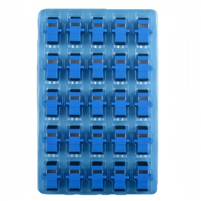
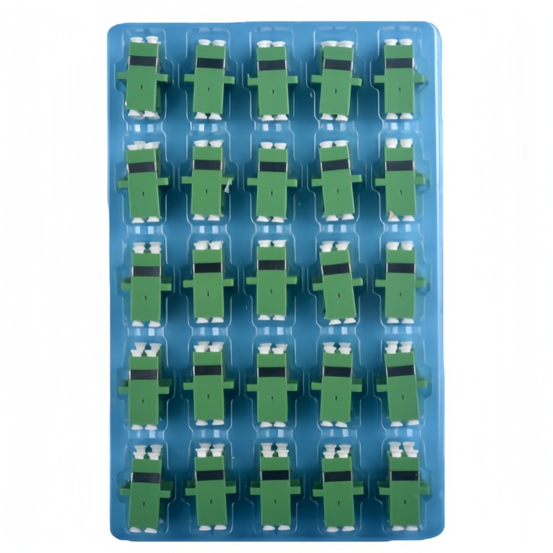
An attenuator carries two end faces, and both have to match the network on either side. UPC end faces are polished flat and typically hold return loss above 50 dB; APC end faces are cut at 8° and hold above 60 dB. In a PON or an analogue video link, where a reflection travelling back up the feeder can upset the laser, APC is the only acceptable choice, and a UPC part in that path degrades the link even though its attenuation value is correct. Mixing the two also damages the angled ferrule, so blue for UPC and green for APC is a working rule rather than decoration. The cords on either side follow the same rule, as set out in the single-mode and multimode patch cord range.
Wavelength is the second compatibility test. Single-mode attenuators are specified at 1310 nm and 1550 nm and multimode parts at 850 nm, and the value is not guaranteed outside that band. In CWDM and DWDM systems the number that matters is wavelength dependent loss: a flat response keeps every channel balanced, while a selective part leaves the band edges at the wrong level. A 50/125 µm multimode attenuator must never go onto 9/125 µm single-mode fiber, and an MPO attenuator reduces all twelve or twenty-four channels of a trunk at once.
What the Specification Sheet Should State
Attenuators are qualified against the same documents as the connectors around them. Telcordia GR-910-CORE covers the attenuator itself, including attenuation accuracy and mechanical durability, while GR-1209-CORE and GR-1221-CORE provide the generic performance and reliability framework for passive components. The IEC 61753-021-2 performance standard fixes the requirements for single-mode fixed attenuators in controlled conditions. Interface dimensions follow IEC 61754, and TIA standards apply where a North American design governs the layup.
| Parameter | Value to ask for | Test reference |
|---|---|---|
| Attenuation accuracy | ±0.5 dB, quoted at 1310 and 1550 nm | IEC 61300-3-4, GR-910-CORE |
| Rückflussdämpfung | ≥50 dB UPC, ≥60 dB APC | IEC 61300-3-6, GR-326-CORE |
| Insertion loss added | <0.5 dB typical for fixed units | IEC 61300-3-4 |
| Wavelength dependent loss | Stated across 1260–1620 nm | IEC 61753-021-2 |
| Power handling | 300 mW or more, higher grades above 1 W | Manufacturer qualification |
| Haltbarkeit der Verbindung | 500 mate cycles with the value still in tolerance | GR-910-CORE, IEC 61753-021-2 |
| Marking | Value and polish on the body, plus a serial-linked test record | Traceability requirement |
Placing Attenuators in a PON or DWDM Design
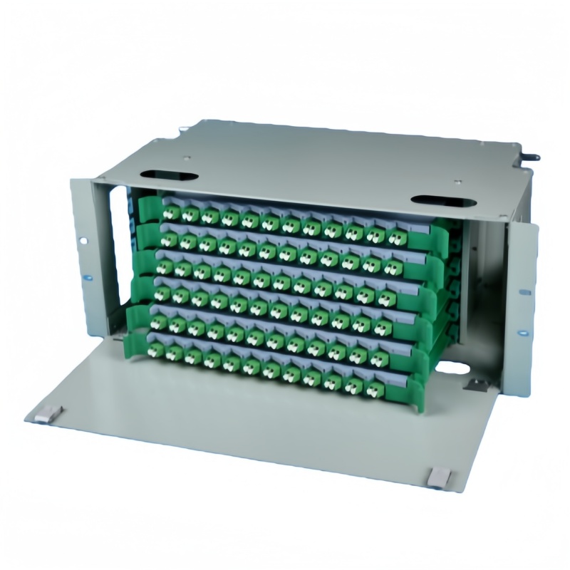
In a PON the attenuator usually belongs at the OLT end rather than at the subscriber, because that is where the excess power sits and where a part can be swapped with rack access. ITU-T G.984.2 defines the optical power classes that set transmitter range and receiver overload points, and it is the reference to quote when the OLT vendor and the PLC-Splitter supplier disagree about who owns the problem. That port feeds an ODF patch field, which is the natural place to keep graded attenuators: a small drawer of 3, 5, 10 and 15 dB parts settles most first-office complaints without a truck roll.
In a WDM system attenuation is a levelling tool rather than a protective one, since amplifier output drifts with channel count and pump ageing. Record the delivered value and the measured received power at each port, so the next engineer can tell whether a drifting link needs a redesign or simply a different attenuator. The Fluke Networks guidance on optical loss budgets follows the same logic of measuring before correcting.
Acceptance Plan at Receipt
A low-cost part that is out of tolerance can invalidate a link test, so a short receiving routine is worth more than the price difference between suppliers. Five steps: 1. Check the marked value against the packing list and confirm that the units in one bag carry the same value rather than a mixture. 2. Verify polish and housing colour against the intended port — UPC to UPC, APC to APC. 3. Measure attenuation at 1310 nm and 1550 nm on a sample of each value. 4. Confirm return loss on the same sample, because a low-grade attenuator with an air gap can meet its dB value and still fail the reflection requirement. 5. Insert one unit into a known-good link and re-run the end-to-end test, which catches interface and keying problems a bench measurement cannot see.
Fenxi supplies fixed and variable attenuators across LC, SC and FC interfaces in UPC and APC polish, shipped with the measured value recorded. Send your link budget, the receiver overload figure and the polish type at each port, and our engineers will confirm the attenuation value and quote the parts against your rollout.