
Use a 0.9 mm boot for compatible 900 µm buffered fibre inside protected enclosures, a 2.0 mm boot for cable assemblies built around an approved 2.0 mm-class jacket and crimp stack, and a 3.0 mm boot only when the cable construction, rear hardware and enclosure clearance support it. The number describes the intended buffer or cable fit, not the glass core, and a larger boot is not automatically stronger or optically better.
Connector boots manage the transition from a relatively rigid connector body to a flexible cable. If the boot bore, length or stiffness does not match the jacket and strength-member capture, the assembly may bend at one sharp point, slip under pull, interfere with adjacent ports or refuse to seat in a dense panel. Buyers should approve the rear assembly as a cross-section and then test the completed cord.
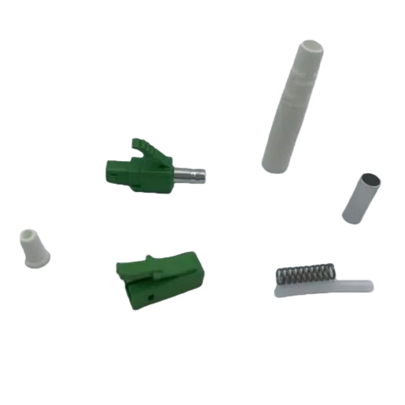
Which Boot Size Fits Which Cable Construction?
Nominal boot sizes are normally discussed by the cable diameter they are intended to accept, but the actual fit depends on jacket tolerance, aramid distribution, crimp hardware and boot geometry. Confirm the supplier’s permitted cable range on its drawing.
| Nominal boot | Typical assembly context | Main design concern | Evidence to request |
|---|---|---|---|
| 0,9 mm | Buffered pigtails in ODFs, cassettes and splice trays | Routing protection without pretending the buffer is a rugged patch cord | Buffer type, bend transition and tray-routing sample |
| 2,0 mm | Compact simplex or duplex patch cords | Balance between port density and repeated handling | Cable cross-section, retention result and panel trial |
| 3,0 mm | Larger cords or assemblies needing a broader rear transition | Clearance behind panels and compatibility with crimp hardware | Rear-body drawing and rack-door clearance check |
| Botte courte | Tight spaces where the cable exits close to the connector | Higher local bend demand if routing is poorly controlled | Minimum routing envelope on the assembly drawing |
| Long boot | Applications that benefit from a gradual bend transition | Greater depth behind the adapter panel | Mated-depth and bend-path mock-up |
What Should Be Checked Before Approving a Boot?
A boot cannot be approved from a catalogue photograph. Review it with the cable, connector body, crimp sleeve and installed panel because each one changes how the rear transition behaves.
Match the full cable tolerance
State the jacket construction and permitted outer-diameter range, not only a nominal diameter. A boot that fits the centre of the range can grip the largest cable too tightly or leave the smallest cable unsupported.
Review strength-member capture
The boot provides bend relief; it should not be treated as the primary tensile member. The drawing needs to show where aramid yarn or another strength member is captured and which crimp part transfers the load into the connector body.
Test the installed routing envelope
Mating depth, latch access, adjacent ports, cabinet doors and cable managers determine whether the assembly fits. A short sample panel exposes clashes that are invisible in an isolated component drawing.
Control material and revision
A change in polymer hardness, mould cavity or boot length can alter handling even when colour and nominal size are unchanged. Put the approved drawing and sample revision on the order and require notice before substitution.
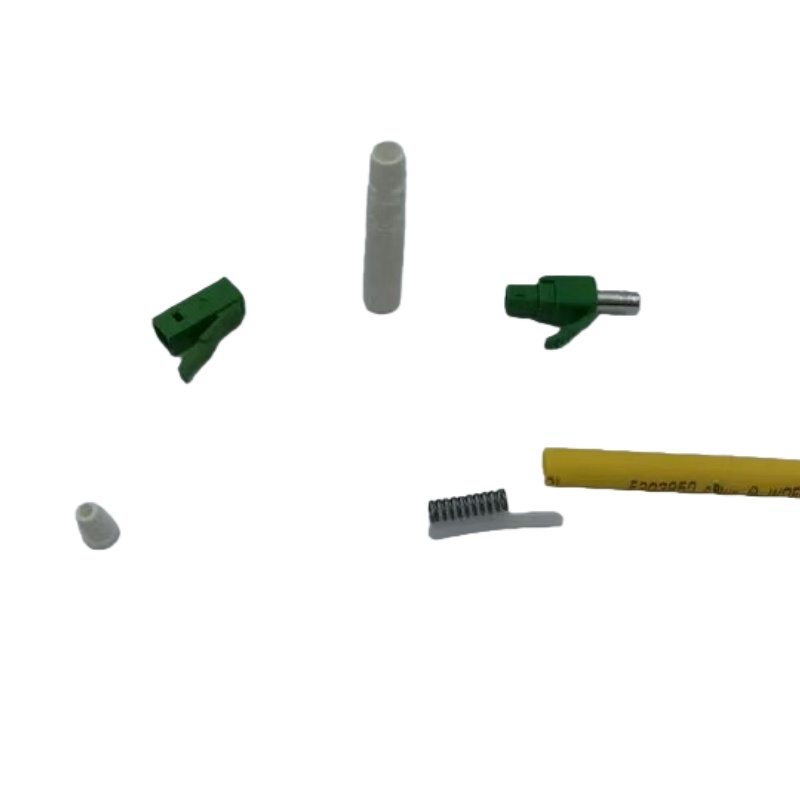
Boot-Related Failures and Their Corrective Controls
The same visible symptom can come from different parts of the rear assembly. Diagnose the load path before changing the boot alone.
| Observed issue | Probable interface | Verification | Corrective control |
|---|---|---|---|
| Cable rotates or pulls back | Crimp sleeve, jacket or strength-member capture | Section a sample and run the specified retention test | Correct crimp stack and tooling |
| Loss changes when cable is dressed | Boot exit and local bend path | Measure while routing through the actual panel geometry | Change boot geometry or cable-management path |
| Latch cannot be reached | Boot and duplex clip crowd adjacent ports | Trial in the target adapter panel | Use the approved short-body or pull-tab arrangement |
| Jacket wrinkles at the boot | Bore or material stiffness does not suit the cable | Inspect after temperature and handling exposure | Approve material and diameter range together |
| Replacement lot feels different | Unannounced material or tooling revision | Compare lot markings, drawing and dimensional report | Enforce change notification and first-article approval |
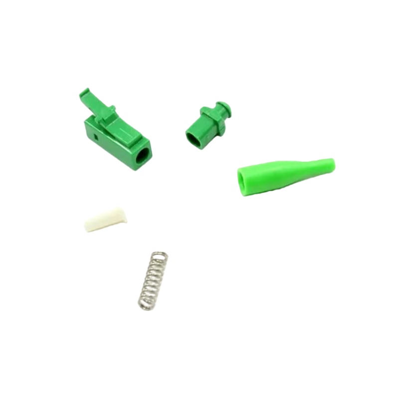
Normes et justificatifs à joindre au bon de commande
The current consolidated LC interface reference is IEC 61754-20:2012+AMD1:2022. It controls the connector interface, while the boot, cable and crimp stack still require assembly-specific approval.
Corning’s current connector-boot catalogue lists 900 µm, 1.6/2.0 mm and 3.0 mm options by connector compatibility, which is a useful cross-check that boot selection belongs to a defined component system rather than a universal colour or size rule.
L'édition 2026 évalue la dégradation optique et mécanique résultant de cycles d'accouplement répétés et intègre des critères de nettoyage et des niveaux de sévérité actualisés. Voir Essai de durabilité d'accouplement selon la norme CEI 61300-2-2:2026.
Corning précise que la norme GR-326 est une spécification de performance applicable aux assemblages complets de connecteurs et de câbles de raccordement monomodes, et non une spécification relative à un composant isolé. Voir Note d'application de Corning sur le GR-326.
A Practical Purchase Decision
Treat 0.9 mm, 2.0 mm and 3.0 mm as assembly families. The correct choice is the one that supports the specified cable, survives the agreed handling test and fits the installed panel without forcing a bend or blocking service access.
- Provide the cable cross-section and diameter tolerance
- State whether the assembly is a protected pigtail or a handled patch cord
- Approve the crimp sleeve and strength-member capture
- Check clearance in the target adapter panel and enclosure
- Retain a signed golden sample for future lot comparison
Pour obtenir un devis sur mesure, consultez le site de Fenxi FC connector components, Gamme de connecteurs LC, SC connector components, et connector ferrule material guide. Veuillez nous communiquer le marché cible, les interfaces de raccordement, le type de fibre, la structure du câble, les quantités, la révision du plan et les rapports d'essais requis. La réponse permettra alors de distinguer les options standard du catalogue des articles nécessitant une confirmation ou un outillage sur mesure.