
A buyer signs off on a fiber bill of materials, a crew pulls the cable, and the link tests 1.5 dB over the calculated budget at handover. The dispatcher blames the installer, the installer blames the connectors, and the engineer pulls the math back out and finds that nobody agreed on what counts as a “connector.” That kind of disagreement is what an insertion loss budget is meant to prevent: a single number the procurement document, the installer acceptance test, and the operations team all work back to. This guide walks through how to build that number for single-mode and multimode fiber links, what reference values to use, and where the math usually breaks in real installations.
What an Insertion Loss Budget Actually Captures
An insertion loss budget is the sum of every expected optical power loss across a passive link: fiber attenuation per kilometre, loss per mated connector pair, and loss per splice. The total becomes the pass-fail benchmark at acceptance testing and the design envelope during engineering. Three things matter most:
- Fiber attenuation over distance at the operating wavelength (1310 nm and 1550 nm for OS2 single-mode; 850 nm for OM3, OM4, OM5 multimode).
- Connector mated-pair loss at the polish grade specified (PC, UPC, or APC).
- Splice loss, with fusion splicing on single-mode and fusion or mechanical splicing on multimode.
The standards that anchor the numbers are TIA-568 for generic cabling, the FOA loss budget reference for engineering practice, IEC 61753-1 for component performance, and Telcordia GR-326 for single-mode connector qualification. Engineers writing a new BOM usually anchor the calculation on TIA-568 worst-case values rather than the factory-typical ones, because acceptance testing has to pass against the worst-case envelope, not the ideal-cleaning numbers on a vendor datasheet.
Component-by-Component Loss: Fiber, Splices, Connectors
Most engineers start by listing every contributor and counting them. For a 10 km FTTH backhaul, that is 2 km of indoor OS2 to the ODF, 8 km of outdoor OS2 to the splitter, plus a PON splitter, and the drop to the customer premises. Each segment has its own fiber, connector, and splice counts, all rolled up into the same total. The discipline is to count every mated pair, every splice, and every metre of fiber, then multiply by the per-unit value from the chosen reference table.
The reference numbers most procurement documents use are TIA-568 worst-case values, not factory-typical numbers. Typical numbers are what the manufacturer claims under ideal cleaning and mating conditions; worst-case numbers are what an acceptance tester with a reference-grade launch cord sees. For a row of patch panels in an ODF, a 12-port LC panel contributes 12 mated pairs, not 12 connectors.
| Component | Typical Loss | TIA-568 Maximum | Reference Standard |
|---|---|---|---|
| OS2 fiber @ 1310 nm | 0.35 dB/km | 0.4 dB/km | ITU-T G.652.D |
| OS2 fiber @ 1550 nm | 0.22 dB/km | 0.3 dB/km | ITU-T G.652.D |
| OM3/OM4 fiber @ 850 nm | 3.0 dB/km | 3.5 dB/km | TIA-568.3-D |
| Fusion splice (single-mode) | 0.05 dB | 0.3 dB | GR-1209 / GR-1221 |
| Mechanical splice | 0.2 dB | 0.3 dB | TIA-568 |
| Mated connector pair (UPC) | 0.2 dB | 0.75 dB | TIA-568 / GR-326 |
| Mated connector pair (APC) | 0.15 dB | 0.75 dB | TIA-568 / GR-326 |
| PLC splitter 1×32 | 16.5 dB | 17.0 dB | GR-1209-CORE |
The same table format works as a procurement spec sheet. List the component, the per-unit loss the vendor must guarantee, the test method, and the reference standard. A line item that says “SC connector, single-mode, UPC polish” without naming the polish grade leaves room for generic PC connectors that intermate but fail any return-loss check above 40 dB.
Connector Loss by Polish Type and Grade
Polish grade is the biggest variable that procurement teams miss when they spec the BOM by connector type alone. An LC connector can be PC, UPC, or APC, and each polish behaves differently in the loss budget and the return-loss budget. UPC is the default for data-center transceivers and most enterprise switches. APC, recognizable by the 8-degree angled end-face, is required for RF-over-fiber, GPON, and any analog video link.
A UPC connector typically returns 50 dB or better; an APC connector returns 60 dB or better. Procurement specs that say “SC connector, single-mode” without naming the polish almost always end up with UPC, fine for digital Ethernet but wrong for analog or RF links.
| Polish | Insertion Loss (typical) | Return Loss | Best-Fit Application |
|---|---|---|---|
| PC (physical contact) | 0.2 dB | 40 dB minimum | Legacy multimode OM1 / OM2 |
| UPC (ultra physical contact) | 0.2 dB | 50 dB minimum | Digital Ethernet, data-center |
| APC (8 degree angled physical contact) | 0.15 dB | 60 dB minimum | RF-over-fiber, GPON, analog video |
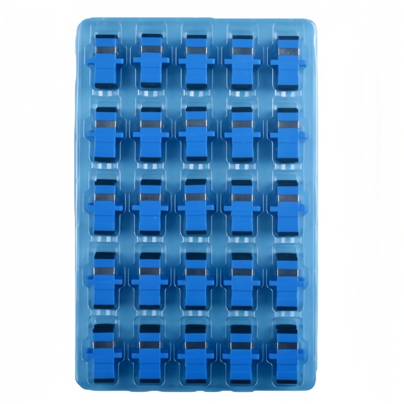
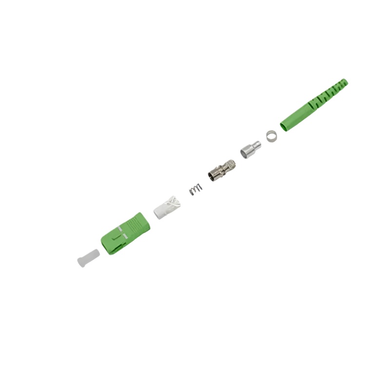
Pair the polish with the adapter color convention: UPC adapters are blue (single-mode) or beige / aqua (multimode), and APC adapters are always green. Buying green fiber optic adapters and UPC SC connectors from different vendors will not intermate, because the ferrule geometry is mechanically incompatible. The same rule applies to LC connector families.
MPO and MTP High-Density Channels: A Different Loss Math
Multi-fiber MPO/MTP channels break the simple “one mated pair equals one connector loss” model. Each MPO connector carries 8, 12, or 24 fibers, and the reference method is a three-cord reference rather than the two-cord reference used for duplex SC and LC. MPO/MTP testing per TIA-568 uses the three-cord method, which is why a single mated pair contributes about 0.35 dB typical and 0.6 dB worst-case, roughly double a single UPC pair.
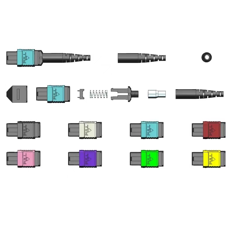
For a 400G-SR8 or 400G-SR4.2 channel running 8 or 4 fibers in parallel, the loss budget compounds across all active fibers plus the MPO-to-LC breakout losses at each end. Field practice is to test each of the 8 fibers independently with a fan-out cord, then compare the worst fiber against the budget. A typical 400G channel through two mated MPO pairs and 30 m of OM4 trunk fiber lands around 2.5 dB insertion loss; IEEE 802.3 allows up to 6 dB for SR8 at 100 m over OM4. Fluke Networks MPO polarity notes walk through the three method-A / B / C options for trunk and breakout polarity.
| MPO/MTP Component | Typical Loss | Maximum per TIA-568 | Notes |
|---|---|---|---|
| MPO mated pair (single-mode) | 0.35 dB | 0.6 dB | Three-cord reference method |
| MPO mated pair (multimode OM4) | 0.30 dB | 0.5 dB | Three-cord reference method |
| MPO-to-LC fanout (per channel) | 0.5 dB | 1.0 dB | Includes 1 mated pair |
| MPO polarity flip (Method B) | + 0.0 dB | + 0.0 dB | No loss penalty if polarity correct |
The polarity rule is a separate engineering check, not a loss budget line item, but it shows up in the same acceptance test. Mismatched polarity between trunk and breakout cords is the most common reason a 400G channel passes fiber continuity but fails link-up.
Worked Example: 10 km FTTH Backhaul at 1310 nm
Putting the math together for a typical rural FTTH backhaul: 10 km of OS2 single-mode cable between the OLT site and a 1×32 PON splitter, with one fusion splice every 2 km (five splices), one mated connector pair at the ODF on each end (two pairs total), and the splitter insertion loss of 16.5 dB.

Step 1, fiber attenuation: 10 km multiplied by 0.4 dB/km equals 4.0 dB.
Step 2, splice loss: 5 splices multiplied by 0.3 dB equals 1.5 dB.
Step 3, connector loss: 2 mated pairs multiplied by 0.75 dB equals 1.5 dB.
Step 4, splitter loss: 1 multiplied by 16.5 dB equals 16.5 dB.
Total passive link loss: 23.5 dB.
For a Class B+ GPON OLT with a 28 dB optical budget, that leaves 4.5 dB for the drop section and ONT margin. The drop, including 500 m of OS2 plus two mated pairs, adds roughly 0.7 dB, well inside the budget. Outdoor fiber termination boxes at the building entry have to be sized against the worst-case budget, not the headline distance.
Decision Tree: How to Build the Insertion Loss Budget for Your Link
Different link types follow different decision paths. Use this tree to pick the right per-component values before opening a spreadsheet.
- If single-mode and longer than 2 km, start from TIA-568 single-mode worst-case values, count every splice every 1 to 2 km, and apply the GR-326 polish grade specified in the BOM.
- If single-mode and shorter than 2 km, fiber attenuation is negligible. The budget is dominated by connector pairs; count each patch panel and breakout as a separate mated pair.
- If multimode OM3 or OM4 in a data-center row, use the 850 nm worst-case (3.5 dB/km) only if the run is over 50 m. Under 50 m, use the typical 3.0 dB/km and budget against the application limit (100GBASE-SR4 = 1.5 dB max channel loss).
- If the link includes an MPO/MTP trunk, use the three-cord reference value, count the MPO-to-LC fanout as a separate loss line, and budget per fiber rather than per trunk.
- If the link includes a PON splitter, add the splitter specified insertion loss (typically 16.5 dB for 1×32, 13.5 dB for 1×16) as a single line item, and budget the rest against the OLT class.
- If FTTA or outdoor 5G, add at least 1 dB of environmental margin for temperature drift, and use IP67-rated fiber termination boxes at every outdoor junction.
The cleanest procurement check is a one-page table that lists every component, the per-unit loss, the count, and the grand total. Anyone who picks up the file, engineer, installer, or auditor, can see where each dB came from. Save that table in the project folder; it becomes the reference for moves and changes over the next decade.
FAQ
Q1. What is a realistic field-tested loss for a brand-new OS2 link with two mated connector pairs?
A: For a 1 km run at 1310 nm, total link loss typically tests between 1.0 and 1.6 dB end-to-end. Anything above 2.0 dB usually means one of the connectors needs cleaning or re-mating.
Q2. How much margin should we leave beyond the calculated budget?
A: TIA-568 already builds in a small engineering margin. Beyond that, allocate 1 dB for aging splices and 0.5 to 1 dB for future moves and changes. The standard rule is 10 to 15 percent of the calculated budget, rounded up.
Q3. Where can I find the official TIA-568 numbers?
A: The TIA-568.0-D, TIA-568.3-D, and TIA-604 series are purchasable from the TIA online store. The Fiber Optic Association loss budget reference lists the same values in a free working-guide format.