
Choose the MPO fibre count from the active interface and lane map, then design trunks, cassettes and polarity around that map. Twelve fibres are not automatically more flexible, and a higher count is not automatically more efficient when lanes remain unused or require special two-row interfaces.
MPO is a connector family with several row and fibre arrangements. The correct selection depends on whether the link uses parallel multimode lanes, parallel single-mode lanes, duplex breakouts or a structured trunk. Procurement needs the connector geometry, pin status, key orientation and polarity in addition to the nominal fibre count.
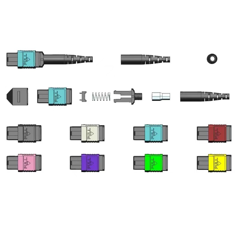
What Must Be Decided for MPO fiber count?
Utilize a tabela de decisão para transformar o tópico em parâmetros controlados de compra, projeto e aceitação. Cada linha deve ser confirmada com base no equipamento real, na rota e no padrão de destino, em vez de ser copiada de um catálogo genérico.
| Área de decisão | O que especificar | Por que isso é importante | Provas a serem mantidas |
|---|---|---|---|
| Active interface | Lane count and optical direction from equipment | Determines live fibres | Transceiver and switch documentation |
| MPO geometry | One-row or two-row interface and width | Controls physical compatibility | IEC 61754 part and drawing |
| Trunk utilization | Live, spare and unused positions | Affects cost and migration | Fibre map by link type |
| Breakout method | Cassette, harness or direct parallel link | Changes connector count and polarity | End-to-end channel diagram |
| Future state | Approved migration rather than vague headroom | Avoids stranded fibres | Signed migration matrix |
How to Control MPO fiber count in the Project
Os controles abaixo relacionam o desenho, a amostra, o lote de produção e o resultado da instalação. Eles são deliberadamente práticos: cada um gera um registro que as equipes de compras, engenharia e de campo podem analisar posteriormente.
Start at the transceiver
Read the equipment interface and lane assignment. Do not infer fibre count from Ethernet speed alone because different optical variants can use different architectures.
Identify rows and pin status
State male or female, key orientation and the applicable one-row or two-row geometry. A mating connector must not be specified by fibre count alone.
Calculate utilization by channel
Map every position through trunk, cassette or harness. Mark unused fibres explicitly so they are not mistaken for spare live paths during commissioning.
Keep migration reversible
Choose modules and trunks that support the documented next interface without creating untestable polarity combinations. Record which components change at each stage.

Verificações de aceitação e entrega
Chegue a um acordo sobre o método e o procedimento antes do início dos testes. Um resultado sem um responsável definido pelo registro ou sem uma ação a ser tomada em caso de falha é difícil de ser utilizado durante a liberação da remessa ou o comissionamento.
| Verificar | Método | Registro | Ação em caso de falha |
|---|---|---|---|
| Interface match | Compare connector drawing to equipment | Approved interface sheet | Stop incompatible order |
| Continuity map | Test every fibre position | Serialized map | Correct or reject crossed fibres |
| Pin and key | Inspect both ends | End-face photographs | Replace wrong gender or orientation |
| Optical result | Test live and required spare fibres | Per-fibre data | Quarantine failing assembly |
| Migration trial | Build one complete target channel | Relatório do piloto | Revise architecture before volume |
Padrões e evidências para fundamentar a ordem de compra
Esta publicação da IEC define as dimensões da interface MPO de duas fileiras. Consulte Interface MPO de duas fileiras conforme a norma IEC 61754-7-2.
Esta publicação da IEC aborda a interface MPO de duas fileiras e 16 fibras. Consulte IEC 61754-7-3: interface MPO com 16 fibras.
Este procedimento da IEC trata dos testes de atenuação, polaridade e comprimento para cabos instalados com terminação MPO. Consulte Procedimento de teste de cabeamento MPO conforme a norma IEC 61280-4-5.
Decision tree
The right MPO count is the smallest documented interface that serves the required lane map and migration path without avoidable stranded positions. Approve it with an end-to-end fibre map.
- Confirm equipment lane map
- Specify MPO rows, pins and key
- Map all fibre positions
- Test each required fibre
- Pilot the planned migration channel
Para obter um orçamento específico para o projeto, consulte a Fenxi’s Linha de conectores MPO, Cabos de conexão MPO/MTP, Guia de especificações para cabos tronco MPO, e Guia de métodos de polaridade MPO. Envie o mercado de destino, as interfaces dos conectores, o tipo de fibra, a construção do cabo, as quantidades, a revisão do desenho e os registros de teste necessários. A resposta poderá, então, distinguir as opções padrão do catálogo dos itens que precisam de confirmação ou de ferramentas personalizadas.