
Engineers and buyers often treat cable management as the last line of a bill of materials, added only after the patch cords and panels are priced. In practice it decides how much of the optical budget survives installation, how quickly a failed link can be found, and whether the rack door still closes after the first hundred connections. The cheapest place to manage fiber is on the purchase order, not with cable ties after handover.

Why Patch Cord Length Is a Design Parameter
A patch cord that is too short pulls tension through the ferrule and the adapter sleeve. The stress shows up first as return loss, then as intermittent registration, and finally as a cracked boot or damaged end face. A cord that is too long is just as expensive: the extra meter has to coil somewhere, and a coil below the cable’s minimum bend radius turns a low-loss jumper into a macrobend loss source. In high-density racks the same excess length blocks airflow, raises inlet temperatures, and makes every future move-add-change a tracing exercise.
The right length is the measured route plus a controlled service loop. Measure the actual path through vertical managers, horizontal fingers and the panel depth, not the straight-line distance between ports. Add roughly 30 cm at each end for re-termination and equipment slide-out. If the route works out to 2.4 m, a 3 m cord is safer than a 2 m cord pulled taut; if it works out to 3.2 m, a 5 m cord leaves two unwanted meters of slack. Standard lengths exist because they cover the bulk of rack and room layouts; custom lengths pay for themselves when the same odd distance repeats across dozens of identical cabinets.
TIA-568.3-D sets the structured-cabling framework that these measurements sit inside, and the TIA web presence links to the standards that govern bend radius, labeling and administration. The optical side is governed by ITU-T G.652 and G.657 for single-mode fibre, and by IEC 60793 for multimode performance. Cable management is not a finishing detail; it is where the physical layer meets the standards.
Bu FOA zarar bütçesi referansı ve Fluke Networks fiber optik kayıp bütçesi guide both start from the same premise: every extra decibel in the link budget has to be paid for somewhere, and poor cable management is a common place to lose it.
Standard Patch Cord Lengths and Where They Belong
| Uzunluk | Tipik kullanım | Routing note |
|---|---|---|
| 0.5 m | Same device face, adjacent ports | Use only when both ports share the same plane |
| 1 m | Same rack unit or adjacent panels | Most common in high-density cabinets |
| 2 m | Same rack, different units | Standard top-of-rack server or switch jumpers |
| 3 m | Adjacent racks or cross-aisle | Includes a 30 cm service loop allowance |
| 5 m | End-of-row or cross-connect | Measure the tray route, not the floor tile count |
| 10 m | Room-to-room or IDF links | Store slack only in radius-controlled loops |
| Custom | Odd distances repeated across many sites | Specify exact meter or fractional length |
The table is a starting point, not a catalogue. A data center that standardizes on 1 m and 3 m cords for 90 percent of its links can keep a smaller spare inventory and reduce the chance that a technician grabs the wrong length because it is the only one left. A telecom cabinet fed from an overhead ladder may need 2 m even for ports in the same rack, because the cord has to drop from the tray, enter the vertical manager and then reach the panel. Write the standard lengths into the installation guide, not just the purchase order.
Bend Radius by Cable Diameter and Fiber Grade
The mechanical bend limit is ten times the cable outer diameter in service, and twenty times while the cord is being pulled or dressed. A 3.0 mm cord therefore needs a 30 mm service radius and a 60 mm installation radius. A 2.0 mm cord halves those numbers, which is why dense panels move to 2.0 mm or 1.6 mm constructions even though the optical performance is unchanged. The table below ties diameter to the practical radius for each cord type.
| Cord or buffer diameter | Service bend radius | Installation bend radius | Typical panel fit |
|---|---|---|---|
| 0.9 mm buffered pigtail | 10 mm | 20 mm | Splice trays and ODF pigtail fields only |
| 1.6 mm uniboot | 16 mm | 32 mm | High-density LC duplex panels |
| 2.0 mm duplex | 20 mm | 40 mm | Dense racks, mixed LC/SC panels |
| 2.4 mm duplex | 24 mm | 48 mm | Legacy SC and mixed panels |
| 3.0 mm duplex | 30 mm | 60 mm | General telecom patching |
Fiber grade changes the optical tolerance, not the mechanical one. Standard single-mode fibre to ITU-T G.652.D tolerates about 30 mm before macrobend loss becomes significant at 1550 nm. Bend-insensitive grades to G.657.A1 and A2 push that limit down toward 10 mm and 7.5 mm, which buys margin at the boot and inside tight trays. The cable jacket and strength members still have their own minimum, so a G.657.A2 cord should not be forced around a 7.5 mm corner; the grade protects the last few centimetres near the connector, not the whole route.

Rack Layout: ODFs, Vertical Managers and Finger Ducts
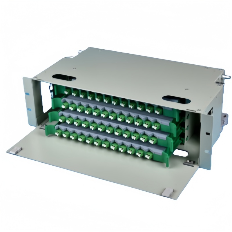
The rack should be planned from the patch field inward. An ODF fiber optik dağıtım panosu terminates feeder cables on the rear and presents adapters on the front, so patch cords leave the frame in a predictable direction and length. Without an ODF, feeder cables are field-spliced or patched directly into active equipment, and every future change risks disturbing a live link. The frame is the anchor that makes the rest of the cable management possible.
Vertical managers keep slack out of the airflow path. A 30 cm service loop belongs behind the equipment, secured with hook-and-loop straps, never with plastic ties that crush the jacket and create microbends. Horizontal finger ducts route cords between panels while maintaining bend radius; rings are cheaper but do nothing to stop a cord from sagging below the allowed radius. The IEC çevrimiçi mağazası publishes the test methods behind connector and cable performance, while the installation practices in TIA standards cover administration and labeling.
Density is a cable-management problem long before it is a cost problem. A 1U panel with 48 duplex LC ports can carry 96 fibers through the front alone. If every cord is a 3.0 mm duplex, the bundle is roughly 60 mm thick before any service loops; the same links in 2.0 mm cord reduce the bundle to 40 mm and let the manager close. The fiber optik adaptör pitch and the cord diameter have to be specified together, because a panel that accepts one may crowd the other.
Slack Storage in Closures and Outdoor Enclosures
Outside the rack, fiber still needs controlled slack. A fiber sonlandırma kutusu at the distribution point stores enough cable to re-terminate a damaged drop without pulling new fiber. A splice closure or cable transfer box stores the mid-span slack between two buried sections. In both cases the spare fiber is coiled in a figure-eight or large-radius tray, never in a tight loop that violates the bend radius.
Outdoor closures add an environmental layer. The IP rating under IEC 60529 tells you whether the closure is dust-tight and how long it can survive immersion, but it says nothing about cable routing inside. A closure rated IP65 can still damage fiber if the installer parks a 5 m service loop in a 100 mm radius. Specify the closure depth and the radius of the internal tray together, and order fiber optik ekleme tepsileri that match the fiber count and buffer size of the cables being stored.
For outdoor equipment interfaces, the cord is usually a factory-terminated assembly of fixed length with a hardened connector. There is no slack to manage at the port, because the assembly is ordered to the exact distance between the enclosure and the active device. The discipline shifts from coiling excess cable to specifying the right length before the order is placed.

Labeling and Documentation That Survives the First Move
A label that falls off after six months is worse than no label, because people trust it and make wrong decisions. Heat-shrink or wrapped polyester labels survive the temperature cycling inside racks and closures better than handwritten tape. A useful label carries origin and destination on the same tag, for example “R12-U24-P03 to R14-U32-P17”, not just a serial number that forces the technician back to a spreadsheet.
Color coding should follow the fibre grade and function, and the scheme should be written on the cabinet door. The conventions in TIA-568 are summarized below.
| Fiber grade or polish | Ceket rengi | Adapter or connector color | Marking |
|---|---|---|---|
| OS2 single-mode UPC | Sarı | Mavi | SM, OS2, UPC |
| OS2 single-mode APC | Sarı | Yeşil | SM, OS2, APC |
| OM3 / OM4 multimode | Aqua | Bej | MM, OM3/OM4 |
| OM5 wideband multimode | Kireç yeşili | Beige or lime | WBMMF, OM5 |
Every move-add-change should update the port map before the technician leaves the row; stale documentation costs more than no documentation because it is trusted.
Summary Recap: What to Specify on the PO
- Route first: measure through managers and trays, not straight-line distance, and add 30 cm at each end for service loops.
- Standardize lengths: keep 1 m, 2 m and 3 m as the default inventory, and specify custom lengths only where the same odd distance repeats.
- Match cord diameter to density: 2.0 mm for dense LC panels, 3.0 mm where handling and bend tolerance matter more than space.
- Respect bend radius: ten times outer diameter in service, twenty times during installation, regardless of fiber grade.
- Use an ODF as the rack anchor: terminate feeder cables on the frame so patch cords leave in a controlled direction and length.
- Store slack with radius control: figure-eight loops in closures, hook-and-loop straps in racks, never plastic ties or tight coils.
- Label for the technician: origin-destination tags, heat-shrink or wrapped polyester, and a color code posted on the cabinet.
Send Fenxi your rack layout, target lengths and fiber count, and we will return a bill of materials covering fiber optik bağlantı kabloları, ODF units, adapter panels, pigtails and splice trays, with lengths and bend-radius notes written against each line.