
A kinked feeder cable passes its OTDR test on handover day and then fails in month nine, when the micro-cracks at the kink finally propagate. By then the duct is backfilled, the acceptance report is signed, and the argument is over whose fault it was. Most of these disputes trace back to four numbers that were on the cable datasheet all along: maximum pulling tension, minimum bend radius under load, minimum radius at rest, and the sidewall pressure the construction can tolerate. Installation volumes make the stakes clear. FTTH Council Europe’s March 2026 forecast projects 353 million FTTH/B premises passed across the EU39 by 2031 (FTTH Council Europe, 2026), and the Fiber Broadband Association reported in December 2025 that the restored 100% bonus depreciation in the United States is expected to lift FTTH capital spending by 5–15% in 2026 (Fiber Broadband Association, 2025). Every one of those kilometres gets pulled, blown or lashed by a crew working against a deadline.
What Bend Radius and Pulling Tension Limits Govern Every Pull?
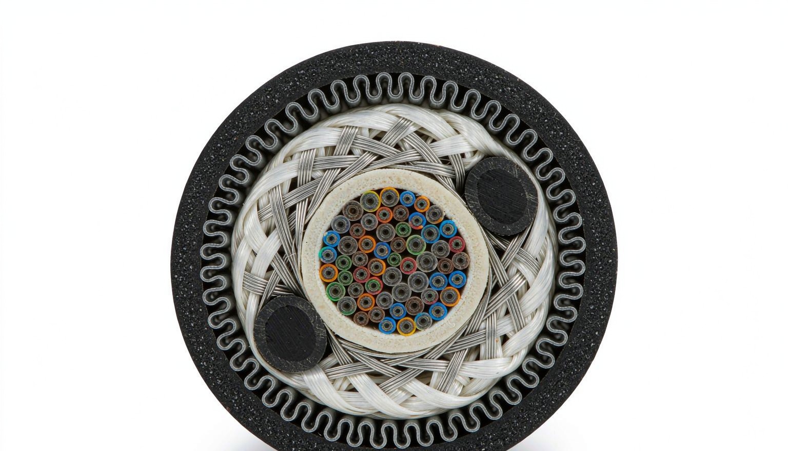
Every fiber cable datasheet carries four mechanical limits — two bend radii and two tension ratings — and the pull plan has to satisfy all of them at the same time.
The industry defaults are 20 times the cable outer diameter under tension and 10 times at rest. Regulators fall back on these when a datasheet is silent: Singapore’s Code of Practice for Telecommunication Wiring Work (2024) requires installers to keep the bend radius at least 20× the cable diameter during placement, with reference to ANSI/TIA-568.3. Watch the radius-versus-diameter trap: a 13 mm cable at 20× needs a 260 mm bend radius, which is a 520 mm diameter sheave — and pulleys and capstans are always specified by diameter. The Fiber Optic Association works the same example and still sees crews size the pulley off the wrong number (FOA outside plant construction guide).
Glass grade bends the rules at the premises end. Under the current UIT-T G.657 edition, A1 fiber is rated to a 10 mm minimum bend radius, A2 and B2 to 7.5 mm, and B3 to 5 mm — but that relaxes the fiber’s tolerance, not the jacket construction’s. A 10 mm loose-tube cable still needs its 100 mm static radius whatever glass is inside, because the buffer tubes and armor do not benefit from bend-insensitive doping. Our earlier G.657 vs G.652 comparison covers where each grade belongs in the network.
Tension ratings differ by market and by construction. North American outside plant practice commonly quotes a short-term installation limit of 2,700 N (600 lbf) with roughly 600 N residual after the pull; construction practice in China commonly quotes 1,500 N short-term for duct and aerial cable and 3,000 N for direct burial. ADSS is specified as a fraction of the cable’s rated tensile strength, typically installed at no more than 20% RTS, because the cable lives under that load for decades. One rule is universal: load goes into the aramid or FRP strength members, which do not stretch — never into the jacket. A jacket grip (Kellems grip) is acceptable only when the manufacturer approves it, and even then it should be tied back to the strength members.
| Cable type (typical OD) | Radius under tension | Radius at rest | Typical install tension range |
|---|---|---|---|
| Patch cord, 2.0–3.0 mm | 40–60 mm | 20–30 mm | 60–150 N |
| Indoor distribution / riser, 8 mm | 160 mm | 80 mm | 600–1,800 N |
| OSP loose tube, 10–13 mm | 200–260 mm | 100–130 mm | up to 2,700 N; ≈600 N long-term |
| FTTH flat drop, 2×3 mm | 30 mm | 15 mm | 400–600 N |
| ADSS aerial, per span design | per datasheet | per datasheet | ≤20% RTS at install |
The ranges above are datasheet planning values, not guarantees; the reel you buy governs. What they do tell a buyer is the scale gap: patch cords downstream of the pull are rated an order of magnitude lower than the feeder itself, which is why factory-terminated cordon de raccordement en fibre optique assemblies are dressed into racks after the pull, never winched through it.
How Do You Estimate Pulling Tension Before the Pull Starts?
Straight duct runs are tension-cheap; bends and lubrication decide whether a pull lands at 250 N or 1,300 N.
Two formulas carry the whole estimate. On a straight run, added tension is the cable weight per metre times the coefficient of friction times the run length: T = μ·w·L. At each change of direction the capstan equation applies: the tension leaving the bend is the tension entering it multiplied by eμθ, where θ is the wrap angle in radians — π/2 for a 90-degree bend. A third number matters at the bends themselves: sidewall pressure, P = T/R, the tension squeezed against each metre of bend radius.
Worked example: an 800 m duct pull of a 24-fiber loose-tube cable weighing about 100 kg/km (w ≈ 1.0 N/m), lubricated, with μ = 0.20 and two 90-degree bends mid-route:
| Segment | Tension entering | Straight-run addition | Bend factor | Tension at exit |
|---|---|---|---|---|
| 0–400 m duct | 0 N | +80 N | — | 80 N |
| 90° bend | 80 N | — | ×1.37 | 110 N |
| 400–600 m duct | 110 N | +40 N | — | 150 N |
| 90° bend | 150 N | — | ×1.37 | 205 N |
| 600–800 m duct | 205 N | +40 N | — | 245 N |
Run the same route dry at μ = 0.5 and the exit tension is about 1,280 N — five times higher, past the 1,500 N short-term rating used for duct cable in much of Asia. The lesson is mechanical, not rhetorical: lubricant and sweep elbows are what keep a routine pull inside the rating, and the two bends contributed more tension than 800 m of straight duct. Sidewall pressure scales the same way. Pushing 245 N around a 0.25 m radius sweep gives P ≈ 980 N/m; forcing the same tension through a 0.15 m standard elbow gives about 1,630 N/m. A widely quoted planning ceiling for fiber cable is 500 lbf/ft (≈7,300 N/m) of bend radius, but the datasheet value governs — and the fix is always a bigger radius, never more force.
Winch practice closes the loop. Cable winches should run from a low start speed, increase gradually (75 m/min is a common maximum), carry a calibrated dynamometer or tension sensor at the winch line, and trip automatically if tension exceeds the preset limit; a breakaway (mechanical fuse) set below the cable’s safe working load is the backup. Steel haul ropes never go into plastic ducts — polyester or aramid rope only — and pulling eyes or grips never pass around a capstan under load. On runs beyond roughly 4 km, plan a mid-span pull and figure-eight the cable on the ground so twist leaves the loop instead of winding into the glass. Past about 120 m (400 ft), or with more than two 90-degree bends, add an intermediate pull box instead of gambling on the estimate.
What Should the Duct Be Checked For Before Cable Enters It?
Most failed pulls are failed pathways: the cable only reports what the duct was hiding.
Prove the pathway first. Rod the duct end to end with fiberglass pushrods, then pull a mandrel sized slightly larger than the cable assembly through it — a mandrel that passes is the cheapest proof that a kinked innerduct or a collapsed section will not eat the cable mid-pull. Every direction change should be a sweep elbow at or above the cable’s dynamic radius, not a standard fitting. Duct ends get capped during construction and sealed with mechanical EPDM seals around the cable afterward; unsealed duct fills with water, silt and insects that turn next year’s additional pull into an excavation.
Fill ratio is where specs get muddled, because two different metrics circulate. North American practice derived from NEC pathway guidance uses area fill: no more than 40% of the duct’s cross-sectional area for the initial cable, 70% absolute maximum. The FOA pulls guidance quotes a cable-to-duct diameter ratio not exceeding 65% for hauling. They agree more than they look like they do: a single cable at 40% area fill corresponds to a diameter ratio of √0.40 ≈ 63%. The practical translations: size innerduct ID to at least twice the cable OD when pulling, and leave one spare conduit alongside every active pathway, because the second cable you pull into a shared duct is the one that tangles a live route.
Air-blown micro cable changes the physics and deserves its own check. Blown installs put near-zero tension on the glass — the cable rides on an air cushion with only 5–15 kg of feed force — but they demand an airtight pathway: aligned couplers, and a test blow of 50–100 m with the actual duct, the actual cable and the actual machine before the production run, recording pressure, cable speed and any stalls. Indoors, respect the fire-rating boundary: NEC Article 770 practice limits outdoor-rated (non-flame-retardant) cable to roughly 15 m (50 ft) inside a building, so plan a splice to indoor-rated cable or specify dual-jacket construction at the entry, and firestop every penetration.
How Do Aerial and Drop Cable Installs Differ from Underground Pulls?
Aerial builds trade a short burst of pulling tension for years of sustained tension, and the design decision is made at the pole, not at the reel.
Figure-8 cable lashed to a steel messenger keeps tension on the messenger, not the glass; keep the messenger on one pole side rather than zigzagging, and bond or ground the strand and any metallic hardware where the route runs near power. ADSS removes the metallic question entirely — all-dielectric, installable near energized lines — but it lives under its own tension: sag-and-tension is calculated per span, installation stays at or below 20% of rated tensile strength, and long-exposure spans need galloping performance. The test for that was revised in April 2026: IEC 60794-1-126:2026 replaced Method E26 from the 2015 edition with updated apparatus and a defined static sag angle for ADSS, OPGW and OPPC cables. When a route crosses wind-exposed spans, ask the supplier for the current-edition galloping report, not a 2015-era certificate.
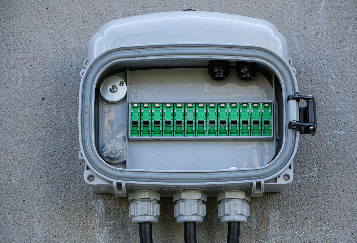
Drop cable is where most subscriber-facing quality is won or lost. Unroll flat drop from the drum edge — never coil it in loops, which winds twist into the ribbon of fibers — and secure it with clips or staples rated for the flat profile at 300–500 mm spacing, tightened no further than the jacket deforms. G.657.A2 or B3 glass carries the 15 mm static radius that building entries and wall boxes actually demand. At the customer wall, regulators increasingly prescribe the termination: Singapore’s 2024 wiring code, for example, requires factory-terminated SC/APC assemblies spliced to the drop, on the logic that a factory polish beats a field polish every time. A wall-mount boîte de terminaison de fibre with pre-terminated pigtails turns that requirement into a ten-minute job with a repeatable loss figure.
Which Tests Turn a Completed Pull into an Accepted Link?
Acceptance runs in three stages, and the stage most often skipped — testing before backfill — is the only one that can still be fixed cheaply.
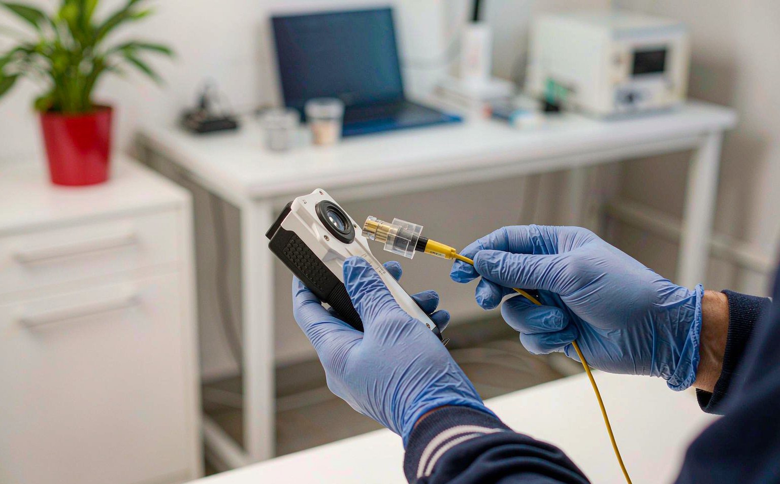
Stage one happens at the reel, before the drum leaves the yard: check the sheath legend against the purchase order, inspect the drum and jacket, and run an on-reel OTDR so any transit damage is the supplier’s problem, not yours. Stage two runs immediately after placement, while the trench is still open and the duct is still accessible: an OTDR at 1310 and 1550 nm, plus 1625 nm where bend exposure matters, with launch and receive leads long enough to cover the instrument’s dead zone. Every event on the trace gets located and identified before the backfill, because a kink found now costs a re-pull of one section and a kink found later costs a fault call. Stage three runs after termination: a Tier 1 insertion loss test at both wavelengths plus end-face inspection of every mated connector to IEC 61300-3-35, the pass/fail zone standard for connector end faces — a dirty end face can add 1–3 dB and will read as a link failure that has nothing to do with the pull.
| Stage | Quand | Test | Common pass criterion |
|---|---|---|---|
| 1. On-reel | At delivery | OTDR per fiber; legend and drum check | Attenuation ≤ datasheet dB/km; legend matches PO |
| 2. Post-placement | Before backfill | OTDR 1310/1550 (+1625 nm), launch + receive leads | All events identified; no bend signatures; total loss ≤ design budget |
| 3. Final | After termination | Tier 1 OLTS both wavelengths; end-face IEC 61300-3-35 | Mated connector ≤0.75 dB; mechanical splice ≤0.3 dB (TIA-568.3-D) |
Fusion splices carry their own target: 0.1 dB or better per joint, with anything above 0.3 dB re-spliced before acceptance. Documentation is the fourth deliverable, and it is contractual: as-built drawings with link IDs and fiber assignments, OTDR trace files stored with the record, and the pull log — tension readings, bend locations, lubricant batch. An operator who keeps those traces has a baseline that cuts fault-location time on every future outage; an operator who filed only pass/fail certificates is re-deriving the plant from scratch at 2 a.m. Test gear selection and limits are covered in depth in our Tier 1 vs Tier 2 testing guide; for end-face criteria, the Fluke Networks fiber inspection reference is a solid bench companion.
Where Do Installation Failures Come From Months After Handover?
Over-tension rarely fails on the day; glass holds the strain until temperature cycling and vibration finish the job.
The recurring modes read back cleanly to the pull record. A kink — cable pulled around a sharp edge or yanked into a tight fitting — sets a permanent deformation in which the glass has already cracked; the OTDR shows a sharp step, often with a reflective peak, and the only repair is cutting the section out and splicing. Over-tension is slower: fiber strain above the proof-test level leaves latent flaws that fracture over three to twelve months, presenting as scattered low-level events rather than one clean break — which is why a re-test six months after handover is standard practice for pulls that ran near the limit. Crush shows up as slowly creeping attenuation at tray edges, ladder rungs and vault brackets. Zip ties cinched until the jacket deforms create the same microbend signature at spacing intervals; the fix is hook-and-loop and a re-test. Water ingress announces itself first at 1550 nm and then at 1625 nm, tracing back to unsealed duct ends or a closure gasket. And jacket choice is a failure mode too: LSZH compounds crack under UV within a couple of seasons outdoors — polyethylene belongs outside, flame-rated compounds belong inside, and the transition belongs at the entry point.
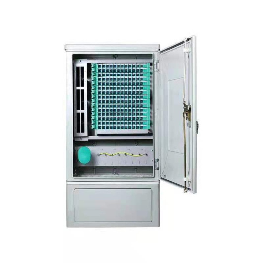
Every one of these modes is preventable at specification time, which is what makes the RFQ the cheapest quality gate in the whole installation.
RFQ Data Sheet: What to Demand from the Cable and Termination Hardware Supplier
A pull plan is only as good as the paper behind it; ask for these line items with every quote and file them with the as-builts.
| Poste de l'appel d'offres | What to specify or demand |
|---|---|
| Mechanical limits per construction | Short-term and long-term tension, dynamic and static bend radius, crush and impact values, all backed by IEC 60794-1-2 test reports |
| Fiber grade and macrobend rating | G.652.D vs G.657.A1/A2 per segment, with minimum bend radius stated against the current ITU-T edition |
| Indoor cable edition | Conformance to IEC 60794-2-20:2025 (4th edition), which added cabled-fiber attenuation requirements and design examples; the IEC 60794 series catalogue sits at the Boutique en ligne de l'IEC |
| Obstruction par l'eau | Gel vs dry (powder/tape) construction, plus water penetration test report |
| Revêtement et résistance au feu | PE outdoors; OFNR/OFNP per NEC Article 770 indoors; UV rating for exposed runs |
| Reel and pull hardware | Reel lengths matched to the pull plan, factory-fitted pulling eyes, drum dimensions for your trailer |
| Documentation relative aux tests | Per-fiber on-reel OTDR traces, attenuation data, and the color code sheet for high-count designs |
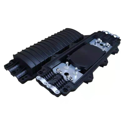
| Termination hardware | Termination boxes, splice trays and ODF panels rated for the cable OD and fan-out used on the route |
| Lead time and packaging | MOQ per reel length, Incoterms, moisture-protected drum packaging |
Fenxi supplies the termination side of the pull: plateaux de raccordement pour fibres optiques, ODF distribution frames, termination boxes and factory-polished patch cords and pigtails built to the grades and polishes your route specifies. Send your pull plan — route lengths, bend schedule, fiber counts and polish types — and our engineers will confirm the termination hardware list and quote to match it before the first drum leaves your yard.
What actually breaks when pulling tension exceeds the cable rating?
Nothing visible, at first. The aramid strength members hold the load, but above the rating the glass inside stretches past its proof-test level, leaving latent surface flaws. Those flaws survive the acceptance OTDR and then fracture over the following three to twelve months under temperature cycling and vibration, which is why over-tensioned pulls get a six-month re-test and why the winch dynamometer, not the crew’s judgment, decides when to stop.
Can you pull fiber optic cable by the jacket with a Kellems grip?
Only when the cable manufacturer explicitly allows it for that construction. The grip must be tied back to the strength members, kept smooth-profiled so it passes duct entries without snagging, and never run around a capstan while under load. If the datasheet is silent, the default is simple: strip the jacket, cut the fibers back, and loop the aramid through a swivel pulling eye in two opposing bundles.
How tight can a patch cord be bent behind a rack?
Use the 10× rule on the cord diameter as the floor: a 2 mm cord holds a 20 mm radius at rest, a 3 mm cord 30 mm. Bend-insensitive G.657 glass relaxes the fiber’s tolerance, but the jacket, buffer and connector backshell do not benefit — and a cord kinked behind a panel adds 0.5 dB or more that only appears at 1550 nm and above. Dress cords with hook-and-loop, never tie wraps.