
Choose simplex when one fibre carries the required optical path or when transmit and receive are intentionally separated. Choose duplex when the equipment interface uses a paired transmit-and-receive channel and the two fibres should be installed, labelled and replaced together. The network architecture decides; connector appearance does not.
A duplex clip can make two simplex connectors look like a single product, but the operational question is whether the two fibres belong to one service path. BiDi optics, monitoring taps, separate protection routes and legacy equipment can all change the answer. Procurement should start from port count and direction, then specify connector, fibre, jacket and polarity.
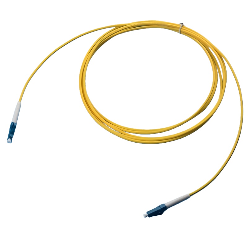
When Is Simplex or Duplex the Better Choice?
Map the optical service first. The table highlights the decision signals without assuming that every Ethernet link or every access link uses the same arrangement.
| Design condition | Simplex choice | Duplex choice | Buyer question |
|---|---|---|---|
| Optical direction | One fibre is sufficient for the defined service or direction | Separate fibres carry transmit and receive | What does the equipment datasheet show at each port? |
| Service grouping | Fibres are managed independently | The pair belongs to one logical link | Should both fibres share one label and replacement part? |
| Routing | Individual paths or physically diverse routes are required | Both fibres follow the same pathway | Does the redundancy design require separation? |
| Connector access | Independent connectors simplify unusual panels | Duplex clips speed paired patching | Can technicians reach both latches in the target panel? |
| Spares | Each fibre can be replaced separately | One stock item restores the full pair | How will spares be identified and stored? |
What Should the Patch-Cord Specification Include?
Once fibre count is settled, the rest of the assembly still needs a controlled definition. A simplex or duplex label alone says nothing about fibre category, polish or polarity.
Match the equipment interface
List the connector at each end, polish, fibre category and equipment port orientation. For a duplex cord, show the A/B map. For a simplex BiDi link, identify the paired wavelengths or device ports in the network documentation rather than on an unsupported cable claim.
Select the cable construction
State jacket material, outer diameter, routing environment and any armouring or breakout requirement. The same connector pair can be built on very different cords, and those cords do not share bend, handling or fire requirements.
Plan identification
Use labels that link the physical cord to the port schedule and test record. Duplex cords need fibre-position labels; simplex services need endpoint and direction identifiers when technicians could interchange them.
Approve replacement logic
Decide whether a duplex assembly must be replaced as a pair and whether a simplex service has a matched spare. This avoids mixing polish, fibre type or polarity during an outage.
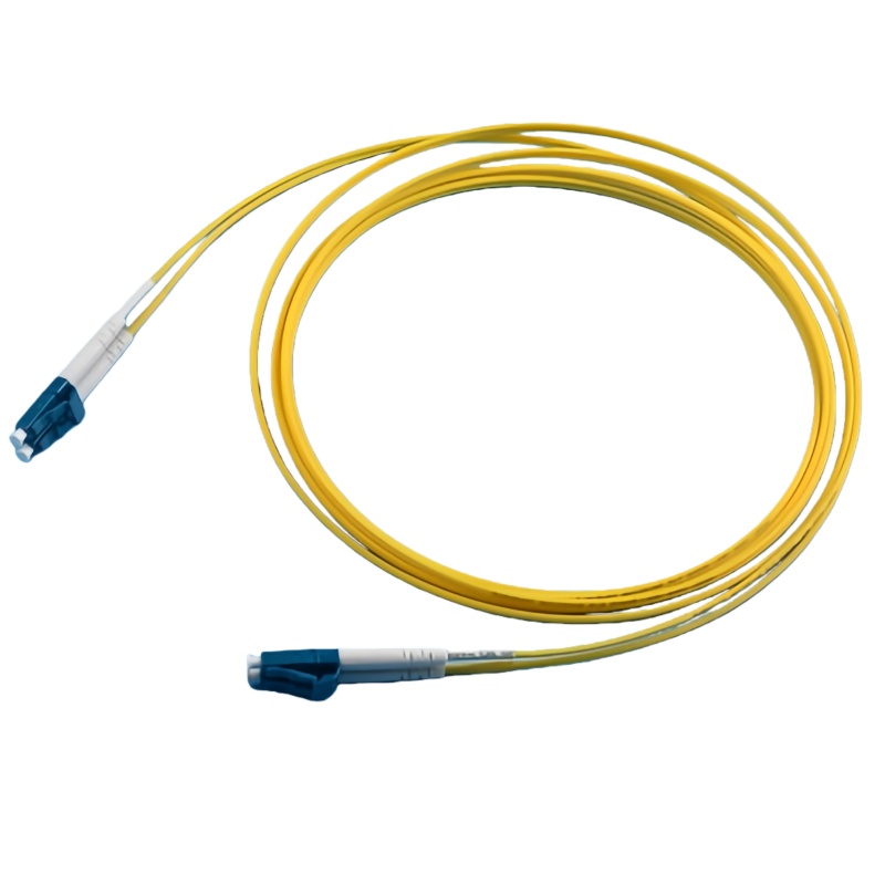
Simplex and Duplex Acceptance Record
The acceptance record should confirm configuration and optical condition separately. A cord can pass loss testing while still being the wrong polarity or fibre type for the equipment.
| Vérifier | Simplex record | Duplex record | Release evidence |
|---|---|---|---|
| Configuration | One fibre identity and endpoint map | Two fibre identities and A/B map | Drawing and serialized label |
| Connector interface | Type and polish at each end | Type, polish and clip arrangement at each end | Visual inspection and bill of materials |
| Fibre category | Declared fibre construction | Same category on both fibres unless specially designed | Material record |
| Optical test | Result for the single path | Result for each fibre, not only an average | Individual test data |
| Emballage | Protection for both end faces | Clip protected and pair kept in final orientation | Sealed package and label check |
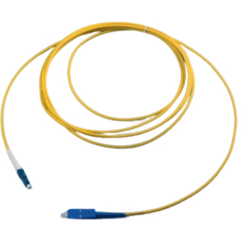
Normes et justificatifs à joindre au bon de commande
The current multimode cabling test standard includes encircled-flux launch conditions and measurement-uncertainty guidance. See IEC 61280-4-1 multimode attenuation test procedure.
L'édition 2024 précise les modalités d'inspection et d'essai des câblages à fibres optiques installés. Voir ISO/IEC 14763-3:2024 — Essais sur les câbles optiques.
FOA distinguishes direct insertion-loss testing from indirect OTDR characterization. See FOA fibre-optic testing reference.
Decision Summary
Simplex and duplex are architectural choices. Start with the equipment’s optical direction and service grouping, then lock the physical assembly, labels and test records to that path.
- Confirm the equipment port map and optical direction
- Decide whether the fibres are managed independently or as one service pair
- Specify fibre category, connector polish and cable construction
- Document duplex polarity or simplex direction labels
- Test and report every fibre individually
Pour obtenir un devis sur mesure, consultez le site de Fenxi fiber optic patch cord range, single-mode patch cords, multimode patch cords, et OS2 and multimode selection guide. Veuillez nous communiquer le marché cible, les interfaces de raccordement, le type de fibre, la structure du câble, les quantités, la révision du plan et les rapports d'essais requis. La réponse permettra alors de distinguer les options standard du catalogue des articles nécessitant une confirmation ou un outillage sur mesure.