
Uma ordem de compra que especifica “cabo para uso externo totalmente dielétrico” e uma lista de materiais que especifica cabo blindado para uso interno geralmente são elaboradas por duas pessoas diferentes, e é nessa discrepância que começam os problemas de aterramento. O vidro em ambos os cabos conduz luz, mas não corrente. A fita de aço, o fio de aço, a barreira de alumínio ou o fio-mensageiro que acompanham o cabo conduzem bem a corrente, e todas as normas elétricas que se aplicam a um trajeto de fibra óptica referem-se a esse metal, e não à fibra propriamente dita.
A exposição não é teórica. O Relatório Anual sobre Raios da Vaisala Xweather, publicado em janeiro de 2026, estimou a atividade de raios nos Estados Unidos em 252 milhões de eventos em 2025, um aumento de 20 % em relação a 2024 e o maior nível em oito anos, com mais de 2 bilhões de eventos detectados em todo o mundo a cada ano. Campanhas de medição instrumentadas em cabos metálicos subterrâneos registraram correntes induzidas da ordem de 100 A decorrentes de descargas ocorridas a uma distância de cerca de 200 m (Paolone et al., Transações do IEEE sobre Compatibilidade Eletromagnética, vol. 47, n.º 3, 2005). Um trajeto cujos elementos metálicos se estendem ininterruptamente até um rack proporciona à corrente um caminho para seguir, e o primeiro ponto que ela atinge é, geralmente, uma bandeja de emendas ou uma gaiola de transceptores.
Por que um cabo de fibra óptica precisa mesmo de aterramento?
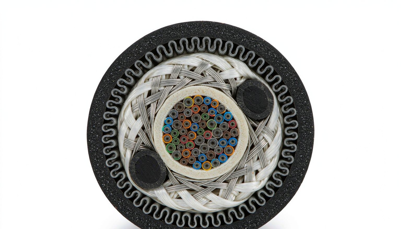
A fibra é um isolante; o cabo construído em torno dela geralmente contém metal, e a ligação à terra proporciona a esse metal um caminho definido para o terra, de modo que a corrente induzida, o contato acidental com a energia elétrica e as diferenças de potencial em relação ao terra não criem seus próprios caminhos. Três mecanismos conduzem corrente elétrica pela estrutura metálica do cabo, e cada um deles é impedido por um detalhe diferente na especificação.
A indução é a forma mais comum. Um raio que atinge uma área próxima à rota induz corrente em qualquer condutor contínuo ao lado da fibra, e a corrente se propaga enquanto o condutor for contínuo. O contato direto é o segundo: instalações externas que compartilham postes com condutores de energia podem acabar entrando em contato com eles após uma falha ou um impacto de veículo, e o metal do cabo fica então no potencial da linha até que algo o ligue. A diferença de potencial em relação ao terra é a terceira e a menos compreendida: dois edifícios em eletrodos separados raramente ficam no mesmo potencial; assim, um cabo blindado que passa entre eles conduz uma corrente estacionária, corrói sua própria blindagem e aquece a junta.
Isso faz com que essa seja uma decisão de aquisição, tomada no momento em que o cabo é encomendado. Um cabo de tubos soltos trançados com fita de aço corrugada, um GYFTY totalmente dielétrico com FRP e aramida e um cabo ADSS sem mensageiro são três opções para o mesmo trajeto, e duas delas vêm acompanhadas de obrigações de ligação. A tabela abaixo apresenta o inventário a ser analisado antes do envio da solicitação de cotação.
| Elemento metálico | Onde aparece | Condutor | O que isso significa para a especificação |
|---|---|---|---|
| Blindagem de fita de aço ondulado | Duto, instalação diretamente enterrada, parte do cabo aéreo | Sim | Faça a ligação no ponto de entrada com uma braçadeira de blindagem ou faça a interrupção com uma junta isolante |
| Blindagem de fio de aço | Passagens subterrâneas há muito enterradas, travessias de rios, trechos subaquáticos | Sim | Fita adesiva; possui seção transversal maior do que a fita, portanto, escolha o tamanho da braçadeira de acordo com o diâmetro da armadura |
| Laminado de alumínio com barreira contra umidade | A maioria dos cabos para uso externo, sob o revestimento | Sim | Faça a ligação como parte da estrutura metálica do cabo; utilize uma transição bimetálica no ponto de contato com o cobre |
| Elemento central de resistência em aço | Alguns cabos da rede externa | Sim | Fixação na estrutura, separada da extremidade da blindagem |
| Elemento central de FRP com fio de aramida | GYFTY totalmente dielétrico, ADSS | Não | Não há caminho de ligação no próprio cabo; as exigências relativas ao chassi e ao rack permanecem |
| Fio de aço para amarração (tipo “8” ou amarrado) | Vãos aéreos | Sim | Condutor contínuo ao longo do vão; ligação na entrada e de acordo com as normas de aterramento da concessionária |
| Fio de rastreamento ou localização | Trajetos com instalação direta no solo | Sim | Divida em seções com juntas isolantes ou trate todo o trajeto como uma instalação metálica |
| Chassi, gaveta e painel adaptador ODF | Sala de equipamentos, instalações da entrada | Sim | Conecte ao ponto de ligação do rack por meio de um condutor específico; as dobradiças não constituem uma ligação |
| Suporte, canaleta para cabos e suporte em escada | Sala de equipamentos, sala de servidores | Sim | Ligação conforme a norma ANSI/TIA-607-E; ponte de ligação em todas as juntas das bandejas |
São duas linhas que causam as controvérsias. O fio traçador é aquele que anula um projeto deliberadamente totalmente dielétrico: um fio de localização contínuo de cobre, colocado sobre um cabo dielétrico e ligado em ambas as extremidades, restabelece o condutor que o projetista se propôs a remover. A questão do chassi do ODF é a segunda, pois a afirmação “o cabo é dielétrico, portanto nada precisa ser ligado” é verdadeira para o cabo, mas falsa para a estrutura metálica na qual o cabo é encaixado.
Quais normas estabelecem essa exigência e o que elas realmente dizem?
Três conjuntos de normas podem ser aplicados a um trecho de cabo, e cada um deles determina o dimensionamento do condutor de maneira diferente: o código elétrico rege os elementos metálicos, a norma de ligação à terra das instalações rege a estrutura e o rack, e as normas de proteção contra raios regem o trajeto. Uma especificação que mencione apenas uma das três deixa as outras duas para serem identificadas na inspeção.
Na América do Norte, a norma NEC 770.93 exigia que os elementos metálicos não condutores de corrente de um cabo de fibra óptica que entrasse em um edifício ou terminasse ao ar livre fossem aterrados de acordo com a norma 770.100 ou isolados por meio de uma junta isolante próxima à entrada. A seção 770.100(A) definia o condutor: cobre ou outro material resistente à corrosão, com espessura não inferior a 14 AWG e não superior a 6 AWG, mantido curto e reto, e com comprimento não superior a 20 pés (6,0 m) em residências unifamiliares e bifamiliares. A edição de 2026 removeu o Artigo 770 e reestruturou o conteúdo sobre energia limitada na faixa de 720 a 750, com os requisitos para cabos de fibra óptica no Artigo 722, o aterramento e a ligação de sistemas de energia limitada reunidos no Artigo 750 e a proteção contra sobretensão no Artigo 742 (consulte a edição atual em NFPA). A adoção ocorre com um atraso de anos em relação à publicação e varia de acordo com a autoridade competente; portanto, verifique qual edição foi utilizada para a inspeção do local antes de citar os números das cláusulas.
No que diz respeito às instalações, a norma é a ANSI/TIA-607-E, publicada em 2024, que também renomeou os componentes de hardware: o barramento de ligação primário (PBB) substitui o barramento de aterramento principal de telecomunicações, o barramento de ligação secundário (SBB) substitui o barramento de aterramento de telecomunicações, o barramento de ligação do rack (RBB) é o barramento no nível do rack e o condutor de ligação da espinha dorsal (BBC) substitui o equalizador de aterramento. Tanto o barramento de ligação quanto o condutor de ligação do rack ou gabinete são especificados com um mínimo de cobre 6 AWG, devem ser instalados de forma contínua, sem emendas, e traçados da maneira mais direta possível, sendo o 3/0 AWG comum em salas de dados (TIA). Projects built to Chinese practice meet GB 50689-2011, where clause 3.6.6 requires the cable’s metallic strength member and metallic protective layer to be earthed in the distribution box or at the ODF earth bar with stranded copper of at least 16 mm², clause 3.9.1 requires crimped or welded copper lugs, and clause 3.14.1 requires indoor cable trays and metalwork to be earthed with every section electrically connected; GB 51120-2015 clause 6.3.3 adds that earthing conductors are laid short and straight, with surplus cut off rather than coiled.
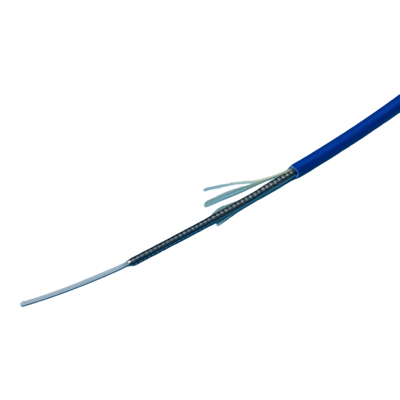
Field practice is more specific than either code. The Fiber Optic Association’s outside plant guide calls for the armor to be lugged and bonded to an earth bar with a soft multi-stranded 6 mm² green/yellow insulated bonding cable, kept as short as practically possible and free of sharp bends, fitted by scoring about 25 mm of outer sheath, sliding the base plate under the armor, fitting the top plate and lock nut, then covering the clamp and the split sheath with vinyl tape (FOA, underground construction).
| Requisito | Fonte | Conductor and hardware |
|---|---|---|
| Bonding of cable metallic members | NEC 770.100(A) (editions to 2023); 2026 edition moves this to the 750 series | Copper or corrosion-resistant conductor, not smaller than 14 AWG, not required larger than 6 AWG; ≤20 ft (6.0 m) for one- and two-family dwellings; terminate at the grounding electrode system or an intersystem bonding termination |
| Armor bond at the cable | FOA outside plant construction guide | Soft multi-stranded 6 mm² green/yellow insulated bonding cable, as short as practical, no sharp bends; armor clamp with base plate, top plate and lock nut |
| Cable metalwork in a telecom building | GB 50689-2011, 3.6.6 and 3.9.1 | Stranded copper ≥16 mm² to the floor or main earth bar, terminated at the ODF earth bar or distribution box; crimped or welded copper lug |
| Rack and cabinet bonding | ANSI/TIA-607-E | ≥6 AWG copper to the RBB or SBB, continuous, no splices, routed directly |
| Bonding backbone | ANSI/TIA-607-E | ≥6 AWG copper minimum; 3/0 AWG typical in data halls |
| Earthing conductor routing | GB 51120-2015, 6.3.3 | Short and straight; surplus cut off, never coiled |
| Surge protection at equipment interfaces | IEC 61643-21:2025 (ed. 2.0), selection per IEC 61643-22, ITU-T K.66 | Specified independently of outside plant cable selection |
| Lightning protection of the line | ITU-T K.47 | Route-level assessment; building-level framework is the IEC 62305 series, whose Part 1 edition 2 no longer covers services connected to structures |
| Bonding inside the building | ITU-T K.27 (telecom building), K.31 (subscriber building), K.35 (remote electronic sites) | Topology and equipotential bonding; protective device selection per ITU-T K.36 |
Where Does Bonding Actually Happen Along the Route?
There are five places, and the one most often missed is the splice where outdoor cable becomes indoor cable. A network can be all-dielectric from the OLT to the building wall and still enter the frame as armored indoor cable, and that armor is a metallic member entering a building, with the same obligation as any outdoor armor.
| Location | What is bonded | Hardware | Evidence to keep |
|---|---|---|---|
| Point of entrance | Armor, metallic strength member and moisture barrier of the incoming cable | Armor clamp or earth kit sized to the cable diameter, bonding conductor to the entrance earth bar or intersystem bonding termination | Photograph of the clamp, measured resistance, conductor size on the packing list |
| Outdoor-to-indoor transition | Metallic members of the indoor section, even where the outdoor section is dielectric | Second armor clamp or an insulating joint at the transition | Continuity reading across the transition; isolation reading if an insulating joint is used |
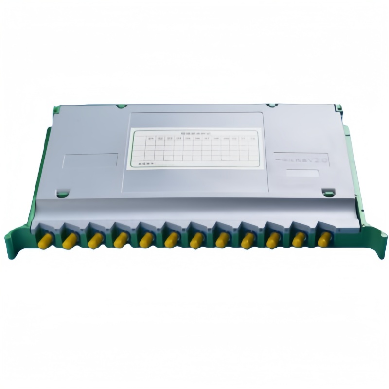
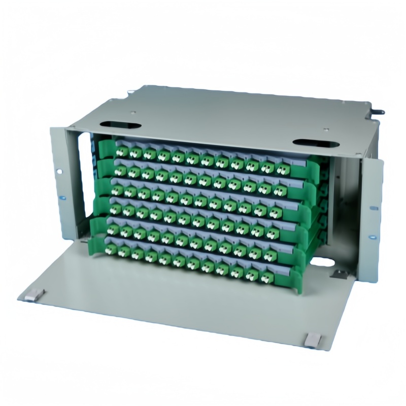
| ODF frame | Chassis, each drawer and the adapter panel metalwork | Dedicated earth stud or earth bar, paint-penetrating washers, braid across each hinged drawer | Frame-to-earth resistance reading; supplier drawing showing the earth point |
| Rack and pathway | Rack frame, tray sections and ladder rack joints | Bonding conductor to the RBB or SBB; jumper at every tray joint | Continuity reading per rack; tray jumper count against the as-built |
| Aerial section | Messenger wire, pole hardware and down leads | Bonding clamps and down leads at the span ends and at the entrance | Pole schedule with earthing notes; utility approval where the poles are shared |
| Joint closures | Armor continuity and the closure earth lug where specified | Armor continuity connector; closure earth terminal | Closure test record; photograph before the closure is sealed |
The insulating joint deserves a note, because it is the code-recognised alternative to bonding and it solves problems bonding cannot. Where a route joins two structures on separate earthing systems, an insulating joint at the entrance removes the circulating-current path instead of trying to carry it, and it removes the obligation to run a heavy bonding conductor to an earth bar that may be 40 m away. The trade is that the metallic member has to remain insulated on both sides, so the joint has to be specified, installed and tested as a separate line item rather than assumed.
What Hardware Does an ODF Frame Need for Bonding?
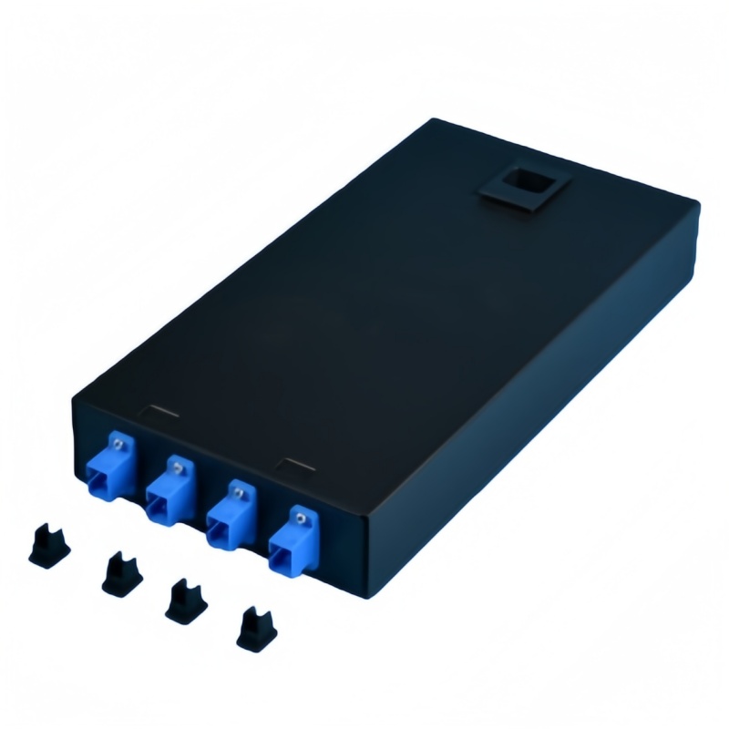
A frame with no designated earth point turns every bonding decision into a field improvisation, and improvisations fail the continuity test eighteen months later. Four items decide whether a frame can be bonded properly, and all four belong on the enquiry rather than in the installation method statement.
First is the earth termination itself: a threaded stud or a short copper bar on the chassis, sized for the lug the specification calls for, with the thread and the lug hole diameter stated on the drawing so the installer does not drill the frame on site. Second is the finish. Powder-coated and painted steel is an insulator, so a bonding point needs paint-penetrating serrated washers or a masked contact area, and a hinged or sliding drawer needs a braided strap because a hinge is a mechanical device, not an electrical bond. Third is conductor routing: the bonding conductor has to reach the earth bar without coiling, without sharp bends and without crossing the fiber management path where it would disturb bend radius. Fourth is the lug and the metals: crimped or welded copper lugs, with a bimetallic transition or anti-oxidant compound wherever an aluminium barrier meets a copper terminal, because that joint corrodes fastest and fails quietest.
Ask the supplier for five things with the quotation: the earth stud thread and lug hole diameter, whether paint-penetrating washers and drawer braids are supplied, the continuity resistance measured between the farthest drawer and the earth stud, the recommended torque for the earth terminal, and a photograph of the earth point on the actual frame. Those five answers separate a frame that can be bonded from a frame that will be argued about at handover.
When Should You Specify All-Dielectric Cable Instead?
Specify all-dielectric cable where the route runs through high lightning activity, shares structures with power conductors or joins two buildings on separate earthing systems; keep metallic armor where rodents, crush load and dig-up risk dominate the route. The two constructions are not interchangeable, and the deciding factor is the threat the armor was bought for.
An all-dielectric cable contains no metal anywhere: no armor, no metallic strength member, no metallic moisture barrier and no messenger. Strength comes from an FRP rod and aramid yarn, and the jacket is polyethylene. GYFTY covers duct and lashed aerial routes; ADSS carries enough aramid to support its own span with no messenger. The standards that apply are ITU-T L.101 (08/2024) for directly buried cable and ITU-T L.102 (11/2025) for aerial cable, with IEC 60794-4-20:2018 as the ADSS family specification and IEEE 1222-2019 as the ADSS test standard that includes electrical surface-degradation testing. That last test matters in one specific place: ADSS on an energised transmission line is at risk from dry-band arcing, which leaves a carbonised and permanently conductive track on the jacket, so the jacket on those spans is selected for electrical stress rather than for lightning.
Lightning protection of the line is the third layer, and it is the one most often miscited. ITU-T K.47 covers protection of telecommunication lines against direct lightning flashes; ITU-T K.25 was withdrawn on 25 January 2013 and its content folded into K.47, so a datasheet that still cites K.25 is working from withdrawn text (ITU-T K.47).
Where a locator wire is needed over a dielectric buried route, it has to be dealt with deliberately. Sectionalizing it with insulating joints at each access point keeps locate capability inside each section while removing the kilometres-long conductor; detectable marking tape or electronic markers give point locations instead of a continuous trace; or the wire stays and the route is designed, bonded and surge-protected as metallic plant. What should not happen is a continuously bonded tracer wire under a design file saying lightning protection was handled by cable selection.
Which Field Failures Come From Skipped Bonding?
Each missed bond leaves a different signature, so the symptom usually tells you which decision to look at. Working backwards from the signature is faster than re-testing the fiber.
An unbonded armor at the entrance shows up as touch voltage on the frame, arcing marks at the armor clamp or a burned jacket where the armor found its own path; a continuity test from armor to earth bar settles it in a minute. A bonding conductor that was left long and coiled does not fail a continuity test at all, which is why it is missed: at transient frequencies the conductor’s inductive reactance dominates and the current side-flashes to nearby metalwork instead of following the wire, so the fix is to shorten and straighten it rather than to upsize it. A frame bonded through paint passes on installation day and fails later, as the joint oxidises under the washer; the same applies to a hinged drawer that was assumed to bond through the hinge. Two buildings with separate electrodes and one armored cable between them produce warmth at the joint and corrosion along the armor, and no amount of fiber testing will show it. Where an aluminium barrier meets a copper lug without a bimetallic transition, the joint goes high-resistance quietly and then fails during the first surge it is asked to carry.
The diagnostic order is short: measure continuity from every metallic member to the earth bar, walk the bonding path for length, coils and painted interfaces, then compare the readings with the design figures before reaching for the optical test set. Optical loss testing and inspection methods for the fiber itself are covered in the reference material from Fluke Networks.
Grounding and Bonding Acceptance Plan
Eight checks, each with a method, a limit and a record, close the gap between a bonding design and a bonding installation. Run them at handover and repeat the first four whenever the frame is extended.
| Verificar | Método | Limit to write into the spec | Registro |
|---|---|---|---|
| Bonding conductor material and size | Visual, compared against the purchase record | Copper, ≥14 AWG under NEC 770.100(A); ≥16 mm² stranded under GB 50689-2011; 6 mm² green/yellow for the armor bond | Material certificate and photograph |
| Armor clamp termination | Visual plus a pull test on the clamp | Clamp seated on the armor, lock nut tight, roughly 25 mm of outer sheath scored, inner sheath undamaged | Photograph before the closure or frame is closed |
| Continuity, armor to earth bar | Low-resistance ohmmeter, four-wire where available | Measured value ≤1 Ω; data halls commonly tighten this to 0.1 Ω | Reading per bond, with the instrument model |
| Rack and frame continuity | Ohmmeter between drawer, chassis and rack bonding point | ≤1 Ω with no dependence on hinges or sliding contacts | Reading per frame and per drawer |
| Conductor routing | Visual | Short, straight, no coils, no sharp bends, clear of the fiber management path | Photograph of each run |
| Insulating joints, where used | Insulation resistance and visual check | No continuity across the joint; isolation maintained on both sides | Reading per joint |
| Lugs and torque | Torque wrench against the manufacturer’s table | Crimped or welded copper lug; bimetallic transition at aluminium-to-copper; torque per the lug maker | Torque record per terminal |
| Electrode and bonding network | Fall-of-potential or clamp-on measurement at the main bar | Measured value compared with the design figure; telecom sites commonly specify 5 Ω or lower | Signed test report and as-built drawing |
Add a re-inspection line to the maintenance schedule while the site is still on the contractor’s warranty: a visual check of every bonding point at least once a year, and a thermographic scan of critical connections where the site cannot tolerate an outage. The scan finds the joint that has gone high-resistance long before it fails.
Does all-dielectric fiber cable need to be grounded?
The cable does not, because there is no conductor in it to ground. The obligations that remain are the metallic members of any other cable entering the same building, the ODF chassis and the rack, and surge protection at the equipment ports. Those three are independent of what the outside plant is made of.
Can an insulating joint replace bonding the armor?
Yes, where the code the site is inspected under allows it. It is the better answer when the route joins two structures on separate earthing systems, or when a bonding conductor would have to run a long way to an earth bar. The joint must be specified and tested as its own line item, with the metallic member insulated on both sides.
What size bonding conductor should the enquiry specify?
Match the figure to the rule the site is inspected under: not smaller than 14 AWG copper and not required to be larger than 6 AWG under NEC 770.100(A), at least 16 mm² stranded copper under GB 50689-2011, a 6 mm² green/yellow stranded bonding cable for the armor itself, and at least 6 AWG for rack and cabinet bonding under ANSI/TIA-607-E. Where two of these apply to one project, take the larger conductor.
Do fiber ports need surge protection if the cable is all-dielectric?
Yes. A transceiver is exposed through its power feed, through copper management and alarm wiring in the same rack and through the chassis bond, so a strike that never came near the fiber route can still arrive at the port. Specify the devices against IEC 61643-21:2025 and select them using IEC 61643-22 or ITU-T K.66, separately from the outside plant cable decision.
Fenxi supplies rack mount optical distribution frames with a designated earth point, outdoor and indoor caixas de terminação de fibra óptica, bandejas de emenda de fibra óptica with metalwork ready for bonding, and cabos de conexão de fibra óptica in armored and dielectric builds. Send the route description, cable construction, destination market and the code edition your authority enforces, and our engineers will return the frame with the earth hardware matched to it, the bonding accessories as separate line items, and the continuity figures with the quotation. Frame fit and rack interface are covered in our guide to 19-inch and 21-inch ODF rack mounting.