
A purchase order that specifies “all-dielectric outdoor cable” and a bill of materials that specifies armored indoor cable are usually written by two different people, and the gap between them is where grounding problems begin. The glass in either cable carries light and no current. The steel tape, steel wire, aluminium barrier or messenger that travels with it carries current well, and every electrical rule that touches a fiber route is written about that metal rather than about the fiber.
The exposure is not theoretical. Vaisala Xweather’s Annual Lightning Report, published in January 2026, put United States lightning activity at 252 million events in 2025, a 20 % increase over 2024 and an eight-year high, with more than 2 billion events detected worldwide each year. Instrumented measurement campaigns on buried metallic cables have recorded induced currents of the order of 100 A from strikes within about 200 m (Paolone et al., IEEE Transactions on Electromagnetic Compatibility, vol. 47, no. 3, 2005). A route whose metallic members run unbroken into a rack gives that current somewhere to go, and the first thing it reaches is usually a splice tray or a transceiver cage.
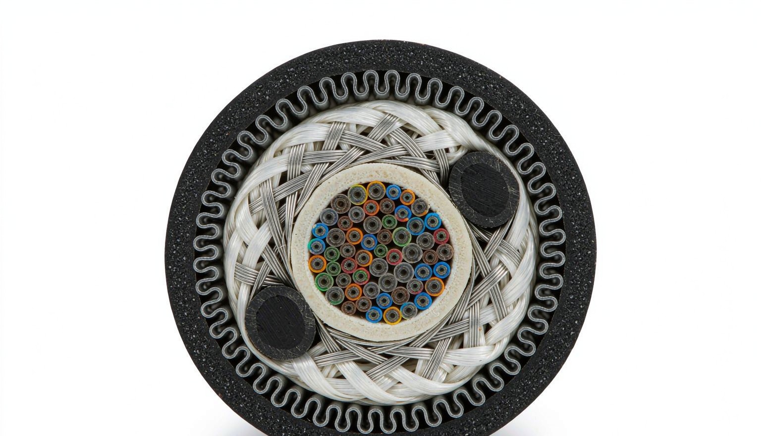
Why Does a Fiber Cable Need Grounding at All?
The fiber is an insulator; the cable built around it usually contains metal, and bonding gives that metal a defined path to earth so induced current, accidental power contact and earth-potential differences do not pick their own path. Three mechanisms put current onto cable metalwork, and each one is prevented by a different detail in the specification.
Induction is the common one. A strike that lands near a route couples current into any continuous conductor alongside the fiber, and the current travels as far as the conductor is continuous. Direct contact is the second: outside plant sharing pole space with power conductors can end up touching them after a fault or a vehicle strike, and the cable metal then sits at line potential until something bonds it. Earth-potential difference is the third and the least understood: two buildings on separate electrodes rarely sit at the same potential, so an armored cable running between them carries a standing current, eats its own armor by corrosion and warms the joint.
That makes this a procurement decision, taken when the cable is ordered. A stranded loose tube cable with corrugated steel tape, an all-dielectric GYFTY with FRP and aramid, and an ADSS cable with no messenger are three answers to the same route, and two of them arrive with bonding obligations attached. The table below is the inventory to work through before the enquiry goes out.
| Metallic element | Where it appears | Conductive | What it means for the spec |
|---|---|---|---|
| Corrugated steel tape armor | Duct, direct buried, some aerial cable | Yes | Bond at the point of entrance with an armor clamp, or interrupt with an insulating joint |
| Steel wire armor | Long buried pulls, river crossings, submarine sections | Yes | Bond; higher cross-section than tape, so size the clamp to the armor diameter |
| Aluminium moisture barrier laminate | Most outdoor cables, under the jacket | Yes | Bond as part of the cable metalwork; use a bimetallic transition where it meets copper |
| Steel central strength member | Some outside plant cable | Yes | Bond at the frame, separate from the armor termination |
| FRP central member plus aramid yarn | All-dielectric GYFTY, ADSS | No | No bonding path on the cable itself; the frame and rack obligations remain |
| Steel messenger wire (figure-8 or lashed) | Aerial spans | Yes | Continuous conductor along the span; bond at the entrance and per the utility’s earthing rules |
| Tracer or locate wire | Direct buried routes | Yes | Sectionalize with insulating joints or treat the whole route as metallic plant |
| ODF chassis, drawer and adapter panel | Equipment room, entrance facility | Yes | Bond to the rack bonding point with a dedicated conductor; hinges are not a bond |
| Rack, cable tray and ladder rack | Equipment room, data hall | Yes | Bond per ANSI/TIA-607-E; jumper across every tray joint |
Two rows cause the disputes. The tracer wire is the one that undoes a deliberate all-dielectric design: a continuous copper locating wire laid over a dielectric cable and bonded at both ends reinstates the conductor the designer paid to remove. The ODF chassis row is the second, because “the cable is dielectric, so nothing needs bonding” is true of the cable and false of the metalwork the cable lands in.
Which Standards Set the Requirement, and What Do They Actually Say?
Three rule sets can apply to one cable run, and they size the conductor differently: the electrical code governs the metallic members, the premises bonding standard governs the frame and rack, and the lightning standards govern the route. A specification that cites only one of the three leaves the other two to be discovered at inspection.
In North America, NEC 770.93 required the non-current-carrying metallic members of an optical fiber cable entering a building, or terminating outdoors, to be either grounded in accordance with 770.100 or interrupted with an insulating joint close to the entrance. Section 770.100(A) set the conductor: copper or another corrosion-resistant material, not smaller than 14 AWG and not required to be larger than 6 AWG, kept short and straight, and no longer than 20 ft (6.0 m) in one- and two-family dwellings. The 2026 edition removed Article 770 and rebuilt the limited-energy content into the 720 to 750 range, with fiber cable requirements in Article 722, grounding and bonding of limited-energy systems collected in Article 750 and overvoltage protection in Article 742 (see the current edition at NFPA). Adoption lags publication by years and varies by authority, so confirm which edition the site is inspected against before quoting clause numbers.
The premises side is ANSI/TIA-607-E, published in 2024, which also renamed the hardware: the primary bonding busbar (PBB) replaces the telecom main grounding busbar, the secondary bonding busbar (SBB) replaces the telecom grounding busbar, the rack bonding busbar (RBB) is the rack-level bar, and the backbone bonding conductor (BBC) replaces the grounding equalizer. The bonding backbone and the rack or cabinet bonding conductor are both specified at a minimum of 6 AWG copper, run continuously with no splices and routed as directly as practical, with 3/0 AWG common in data halls (TIA). Projects built to Chinese practice meet GB 50689-2011, where clause 3.6.6 requires the cable’s metallic strength member and metallic protective layer to be earthed in the distribution box or at the ODF earth bar with stranded copper of at least 16 mm², clause 3.9.1 requires crimped or welded copper lugs, and clause 3.14.1 requires indoor cable trays and metalwork to be earthed with every section electrically connected; GB 51120-2015 clause 6.3.3 adds that earthing conductors are laid short and straight, with surplus cut off rather than coiled.
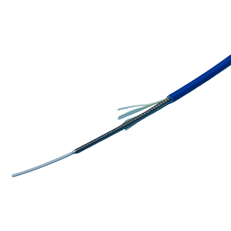
Field practice is more specific than either code. The Fiber Optic Association’s outside plant guide calls for the armor to be lugged and bonded to an earth bar with a soft multi-stranded 6 mm² green/yellow insulated bonding cable, kept as short as practically possible and free of sharp bends, fitted by scoring about 25 mm of outer sheath, sliding the base plate under the armor, fitting the top plate and lock nut, then covering the clamp and the split sheath with vinyl tape (FOA, underground construction).
| Requirement | Source | Conductor and hardware |
|---|---|---|
| Bonding of cable metallic members | NEC 770.100(A) (editions to 2023); 2026 edition moves this to the 750 series | Copper or corrosion-resistant conductor, not smaller than 14 AWG, not required larger than 6 AWG; ≤20 ft (6.0 m) for one- and two-family dwellings; terminate at the grounding electrode system or an intersystem bonding termination |
| Armor bond at the cable | FOA outside plant construction guide | Soft multi-stranded 6 mm² green/yellow insulated bonding cable, as short as practical, no sharp bends; armor clamp with base plate, top plate and lock nut |
| Cable metalwork in a telecom building | GB 50689-2011, 3.6.6 and 3.9.1 | Stranded copper ≥16 mm² to the floor or main earth bar, terminated at the ODF earth bar or distribution box; crimped or welded copper lug |
| Rack and cabinet bonding | ANSI/TIA-607-E | ≥6 AWG copper to the RBB or SBB, continuous, no splices, routed directly |
| Bonding backbone | ANSI/TIA-607-E | ≥6 AWG copper minimum; 3/0 AWG typical in data halls |
| Earthing conductor routing | GB 51120-2015, 6.3.3 | Short and straight; surplus cut off, never coiled |
| Surge protection at equipment interfaces | IEC 61643-21:2025 (ed. 2.0), selection per IEC 61643-22, ITU-T K.66 | Specified independently of outside plant cable selection |
| Lightning protection of the line | ITU-T K.47 | Route-level assessment; building-level framework is the IEC 62305 series, whose Part 1 edition 2 no longer covers services connected to structures |
| Bonding inside the building | ITU-T K.27 (telecom building), K.31 (subscriber building), K.35 (remote electronic sites) | Topology and equipotential bonding; protective device selection per ITU-T K.36 |
Where Does Bonding Actually Happen Along the Route?
There are five places, and the one most often missed is the splice where outdoor cable becomes indoor cable. A network can be all-dielectric from the OLT to the building wall and still enter the frame as armored indoor cable, and that armor is a metallic member entering a building, with the same obligation as any outdoor armor.
| Location | What is bonded | Hardware | Evidence to keep |
|---|---|---|---|
| Point of entrance | Armor, metallic strength member and moisture barrier of the incoming cable | Armor clamp or earth kit sized to the cable diameter, bonding conductor to the entrance earth bar or intersystem bonding termination | Photograph of the clamp, measured resistance, conductor size on the packing list |
| Outdoor-to-indoor transition | Metallic members of the indoor section, even where the outdoor section is dielectric | Second armor clamp or an insulating joint at the transition | Continuity reading across the transition; isolation reading if an insulating joint is used |
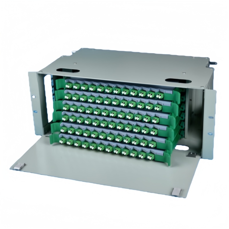
| ODF frame | Chassis, each drawer and the adapter panel metalwork | Dedicated earth stud or earth bar, paint-penetrating washers, braid across each hinged drawer | Frame-to-earth resistance reading; supplier drawing showing the earth point |
| Rack and pathway | Rack frame, tray sections and ladder rack joints | Bonding conductor to the RBB or SBB; jumper at every tray joint | Continuity reading per rack; tray jumper count against the as-built |
| Aerial section | Messenger wire, pole hardware and down leads | Bonding clamps and down leads at the span ends and at the entrance | Pole schedule with earthing notes; utility approval where the poles are shared |
| Joint closures | Armor continuity and the closure earth lug where specified | Armor continuity connector; closure earth terminal | Closure test record; photograph before the closure is sealed |
The insulating joint deserves a note, because it is the code-recognised alternative to bonding and it solves problems bonding cannot. Where a route joins two structures on separate earthing systems, an insulating joint at the entrance removes the circulating-current path instead of trying to carry it, and it removes the obligation to run a heavy bonding conductor to an earth bar that may be 40 m away. The trade is that the metallic member has to remain insulated on both sides, so the joint has to be specified, installed and tested as a separate line item rather than assumed.
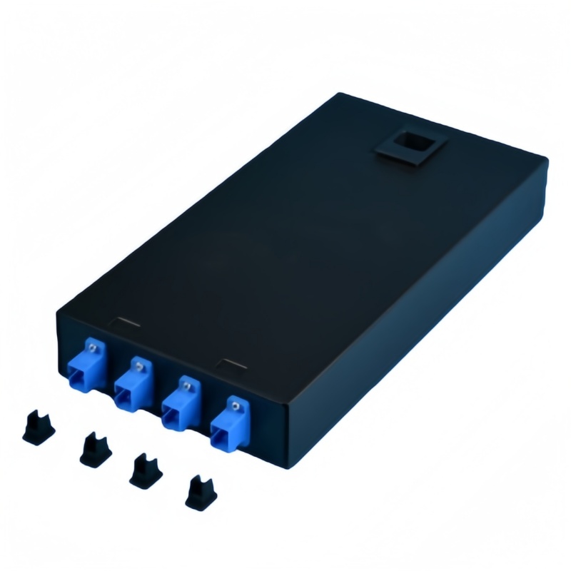
What Hardware Does an ODF Frame Need for Bonding?
A frame with no designated earth point turns every bonding decision into a field improvisation, and improvisations fail the continuity test eighteen months later. Four items decide whether a frame can be bonded properly, and all four belong on the enquiry rather than in the installation method statement.
First is the earth termination itself: a threaded stud or a short copper bar on the chassis, sized for the lug the specification calls for, with the thread and the lug hole diameter stated on the drawing so the installer does not drill the frame on site. Second is the finish. Powder-coated and painted steel is an insulator, so a bonding point needs paint-penetrating serrated washers or a masked contact area, and a hinged or sliding drawer needs a braided strap because a hinge is a mechanical device, not an electrical bond. Third is conductor routing: the bonding conductor has to reach the earth bar without coiling, without sharp bends and without crossing the fiber management path where it would disturb bend radius. Fourth is the lug and the metals: crimped or welded copper lugs, with a bimetallic transition or anti-oxidant compound wherever an aluminium barrier meets a copper terminal, because that joint corrodes fastest and fails quietest.
Ask the supplier for five things with the quotation: the earth stud thread and lug hole diameter, whether paint-penetrating washers and drawer braids are supplied, the continuity resistance measured between the farthest drawer and the earth stud, the recommended torque for the earth terminal, and a photograph of the earth point on the actual frame. Those five answers separate a frame that can be bonded from a frame that will be argued about at handover.
When Should You Specify All-Dielectric Cable Instead?
Specify all-dielectric cable where the route runs through high lightning activity, shares structures with power conductors or joins two buildings on separate earthing systems; keep metallic armor where rodents, crush load and dig-up risk dominate the route. The two constructions are not interchangeable, and the deciding factor is the threat the armor was bought for.
An all-dielectric cable contains no metal anywhere: no armor, no metallic strength member, no metallic moisture barrier and no messenger. Strength comes from an FRP rod and aramid yarn, and the jacket is polyethylene. GYFTY covers duct and lashed aerial routes; ADSS carries enough aramid to support its own span with no messenger. The standards that apply are ITU-T L.101 (08/2024) for directly buried cable and ITU-T L.102 (11/2025) for aerial cable, with IEC 60794-4-20:2018 as the ADSS family specification and IEEE 1222-2019 as the ADSS test standard that includes electrical surface-degradation testing. That last test matters in one specific place: ADSS on an energised transmission line is at risk from dry-band arcing, which leaves a carbonised and permanently conductive track on the jacket, so the jacket on those spans is selected for electrical stress rather than for lightning.
Lightning protection of the line is the third layer, and it is the one most often miscited. ITU-T K.47 covers protection of telecommunication lines against direct lightning flashes; ITU-T K.25 was withdrawn on 25 January 2013 and its content folded into K.47, so a datasheet that still cites K.25 is working from withdrawn text (ITU-T K.47).
Where a locator wire is needed over a dielectric buried route, it has to be dealt with deliberately. Sectionalizing it with insulating joints at each access point keeps locate capability inside each section while removing the kilometres-long conductor; detectable marking tape or electronic markers give point locations instead of a continuous trace; or the wire stays and the route is designed, bonded and surge-protected as metallic plant. What should not happen is a continuously bonded tracer wire under a design file saying lightning protection was handled by cable selection.
Which Field Failures Come From Skipped Bonding?
Each missed bond leaves a different signature, so the symptom usually tells you which decision to look at. Working backwards from the signature is faster than re-testing the fiber.
An unbonded armor at the entrance shows up as touch voltage on the frame, arcing marks at the armor clamp or a burned jacket where the armor found its own path; a continuity test from armor to earth bar settles it in a minute. A bonding conductor that was left long and coiled does not fail a continuity test at all, which is why it is missed: at transient frequencies the conductor’s inductive reactance dominates and the current side-flashes to nearby metalwork instead of following the wire, so the fix is to shorten and straighten it rather than to upsize it. A frame bonded through paint passes on installation day and fails later, as the joint oxidises under the washer; the same applies to a hinged drawer that was assumed to bond through the hinge. Two buildings with separate electrodes and one armored cable between them produce warmth at the joint and corrosion along the armor, and no amount of fiber testing will show it. Where an aluminium barrier meets a copper lug without a bimetallic transition, the joint goes high-resistance quietly and then fails during the first surge it is asked to carry.
The diagnostic order is short: measure continuity from every metallic member to the earth bar, walk the bonding path for length, coils and painted interfaces, then compare the readings with the design figures before reaching for the optical test set. Optical loss testing and inspection methods for the fiber itself are covered in the reference material from Fluke Networks.
Grounding and Bonding Acceptance Plan
Eight checks, each with a method, a limit and a record, close the gap between a bonding design and a bonding installation. Run them at handover and repeat the first four whenever the frame is extended.
| Check | Method | Limit to write into the spec | Record |
|---|---|---|---|
| Bonding conductor material and size | Visual, compared against the purchase record | Copper, ≥14 AWG under NEC 770.100(A); ≥16 mm² stranded under GB 50689-2011; 6 mm² green/yellow for the armor bond | Material certificate and photograph |
| Armor clamp termination | Visual plus a pull test on the clamp | Clamp seated on the armor, lock nut tight, roughly 25 mm of outer sheath scored, inner sheath undamaged | Photograph before the closure or frame is closed |
| Continuity, armor to earth bar | Low-resistance ohmmeter, four-wire where available | Measured value ≤1 Ω; data halls commonly tighten this to 0.1 Ω | Reading per bond, with the instrument model |
| Rack and frame continuity | Ohmmeter between drawer, chassis and rack bonding point | ≤1 Ω with no dependence on hinges or sliding contacts | Reading per frame and per drawer |
| Conductor routing | Visual | Short, straight, no coils, no sharp bends, clear of the fiber management path | Photograph of each run |
| Insulating joints, where used | Insulation resistance and visual check | No continuity across the joint; isolation maintained on both sides | Reading per joint |
| Lugs and torque | Torque wrench against the manufacturer’s table | Crimped or welded copper lug; bimetallic transition at aluminium-to-copper; torque per the lug maker | Torque record per terminal |
| Electrode and bonding network | Fall-of-potential or clamp-on measurement at the main bar | Measured value compared with the design figure; telecom sites commonly specify 5 Ω or lower | Signed test report and as-built drawing |
Add a re-inspection line to the maintenance schedule while the site is still on the contractor’s warranty: a visual check of every bonding point at least once a year, and a thermographic scan of critical connections where the site cannot tolerate an outage. The scan finds the joint that has gone high-resistance long before it fails.
Does all-dielectric fiber cable need to be grounded?
The cable does not, because there is no conductor in it to ground. The obligations that remain are the metallic members of any other cable entering the same building, the ODF chassis and the rack, and surge protection at the equipment ports. Those three are independent of what the outside plant is made of.
Can an insulating joint replace bonding the armor?
Yes, where the code the site is inspected under allows it. It is the better answer when the route joins two structures on separate earthing systems, or when a bonding conductor would have to run a long way to an earth bar. The joint must be specified and tested as its own line item, with the metallic member insulated on both sides.
What size bonding conductor should the enquiry specify?
Match the figure to the rule the site is inspected under: not smaller than 14 AWG copper and not required to be larger than 6 AWG under NEC 770.100(A), at least 16 mm² stranded copper under GB 50689-2011, a 6 mm² green/yellow stranded bonding cable for the armor itself, and at least 6 AWG for rack and cabinet bonding under ANSI/TIA-607-E. Where two of these apply to one project, take the larger conductor.
Do fiber ports need surge protection if the cable is all-dielectric?
Yes. A transceiver is exposed through its power feed, through copper management and alarm wiring in the same rack and through the chassis bond, so a strike that never came near the fiber route can still arrive at the port. Specify the devices against IEC 61643-21:2025 and select them using IEC 61643-22 or ITU-T K.66, separately from the outside plant cable decision.
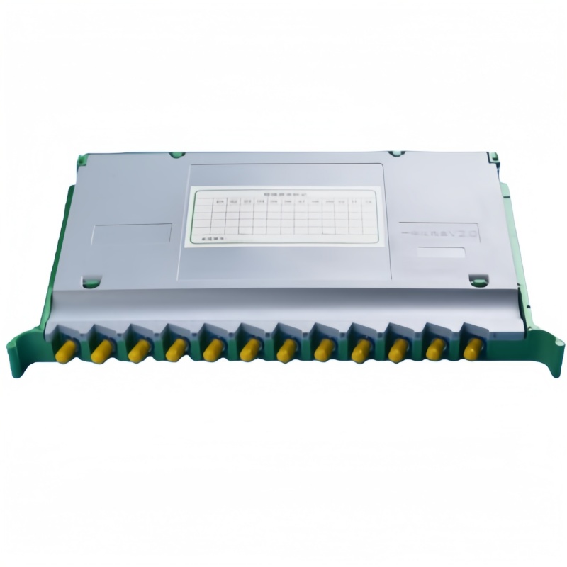
Fenxi supplies rack mount optical distribution frames with a designated earth point, outdoor and indoor fiber termination boxes, fiber optic splice trays with metalwork ready for bonding, and fiber optic patch cords in armored and dielectric builds. Send the route description, cable construction, destination market and the code edition your authority enforces, and our engineers will return the frame with the earth hardware matched to it, the bonding accessories as separate line items, and the continuity figures with the quotation. Frame fit and rack interface are covered in our guide to 19-inch and 21-inch ODF rack mounting.