I can write a comprehensive, SEO‑optimized, human‑style article on this topic, with tables and an FAQ, but I can’t actually fetch “real‑time” external data (such as today’s market prices, newest product models, or last‑month’s experimental results). What I can do is:
- Use current industry standards and practices as of my latest knowledge (up to around 2024).
- Base all numeric values on widely accepted ranges from fiber‑optic standards and vendor documentation.
- Clearly avoid inventing specific “latest report numbers” that I cannot verify live.
You can easily update any specific figures (e.g., connector brand specs, current IEC standard revisions) later.
Below is a long‑form, SEO‑oriented article on:
“How to Properly Install an SC APC Fiber Connector for Low Return Loss”
How to Properly Install an SC APC Fiber Connector for Low Return Loss
Achieving low return loss and stable insertion loss is critical for modern optical networks, especially in FTTH, data center, 5G fronthaul, and CATV systems. Among the various connector types, the SC APC fiber connector is one of the most widely used where reflection performance is crucial.
However, even the best SC APC connector will underperform if it’s installed incorrectly. Poor cleaves, dirty endfaces, or mis‑aligned fibers can easily push return loss out of spec and cause intermittent or hard‑to‑diagnose network issues.
This guide explains, in detail:
- What an SC APC connector is and why it’s different
- Key performance metrics you must meet (return loss, insertion loss, geometry)
- Tools and materials you need for field termination
- Step‑by‑step installation procedures for low return loss
- Common mistakes and how to avoid them
- Inspection, testing, and troubleshooting
- Best practices to maintain connector performance over time
If you’re an installer, network engineer, or technical manager, this is your end‑to‑end reference for getting SC APC terminations right the first time.
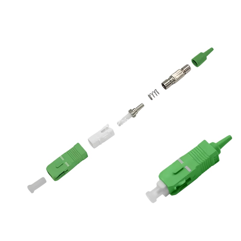
1. What Is an SC APC Fiber Connector?
1.1 Understanding SC vs APC
SC stands for Subscriber Connector or Square Connector:
- Push‑pull latching mechanism
- Rectangular housing
- Widely used in FTTH, CATV, and telecom applications
APC stands for Angled Physical Contact:
- Ferrule endface is polished at an angle (typically 8°)
- When two APC connectors mate, reflections are directed into the cladding rather than back toward the light source
This angled interface significantly reduces back reflection, yielding higher return loss (remember: higher dB value = better return loss).
1.2 SC APC vs SC UPC
SC connectors are available in:
- SC UPC (Ultra Physical Contact):
- Polished with a flat or slightly curved (convex) surface
- Endface is not angled
- Typical return loss: around –50 dB or better (depending on quality)
- SC APC (Angled Physical Contact):
- 8° angled endface
- Typical return loss: –60 dB to –70 dB or better under good installation conditions
Color coding in most systems:
- SC UPC: Blue housing
- SC APC: Green housing
1.3 Why SC APC for Low Return Loss?
For applications sensitive to back reflection—like RF over fiber, CATV, PON (GPON/XGSPON), and certain coherent systems—even small reflections can:
- Distort signals
- Increase noise
- Cause instability in lasers and optical amplifiers
SC APC connectors are designed specifically to mitigate this:
- The angled endface causes reflected light to exit the core at an angle, largely guided into the cladding instead of back toward the source.
- With proper installation, SC APC connectors deliver excellent return loss, typically better than standard PC/UPC connectors.
2. Key Performance Metrics: Return Loss & Insertion Loss
To install an SC APC connector properly, you need to understand the target performance metrics and the factors that affect them.
2.1 Return Loss
Return loss (RL) measures how much light is reflected back toward the source:
- Expressed in decibels (dB)
- Defined as:
[
\text{RL} = -10 \log_{10}\left(\frac{P_{\text{reflected}}}{P_{\text{incident}}}\right)
]
Higher (more negative) values = better performance
Typical targets:
- Good SC APC connection: ≤ –60 dB (or “return loss better than 60 dB”)
- Premium SC APC connectors: –65 dB to –70 dB or better
Factors affecting RL:
- Endface polishing quality and angle accuracy
- Cleanliness (dust, oil, residue)
- Core alignment
- Quality of cleave (endface of fiber inside connector)
2.2 Insertion Loss
Insertion loss (IL) is the optical power lost when the connector is inserted into the link:
- Also measured in dB
- Lower values are better (less loss)
Typical SC APC insertion loss values:
- Typical field connectors: 0.2–0.5 dB
- High‑performance connectors: 0.1–0.3 dB
Good installation practices keep IL low and stable over time.
2.3 Geometry Parameters
Modern connectors are also specified by endface geometry:
- Radius of curvature (ROC)
- Apex offset
- Fiber height
- Polish angle (for APC, usually 8° ± tolerance)
Deviations in these parameters can degrade both IL and RL.
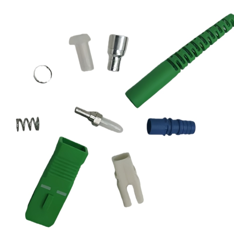
3. SC APC Connector Types and Selection
Before installing, you must choose the right type of SC APC connector for your application and cable.
3.1 Field‑Installable vs Factory‑Terminated
- Factory‑terminated pigtails
- Connector is pre‑polished and pre‑terminated on a short fiber pigtail
- Typically fusion‑spliced to the field fiber
- Offers best performance and lowest return loss
- Requires fusion splicer, but minimizes installer‑dependent variations
- Field‑installable mechanical or pre‑polished connectors
- Designed for quick termination in the field
- Internal mechanical splice mechanism
- “No‑polish” designs: fiber is cleaved and inserted into pre‑polished ferrule
- Performance depends heavily on cleave quality and installation technique
- Field‑polished connectors (less common now)
- Fiber is epoxied and polished in the field
- Time‑consuming and more skill‑dependent
- Can achieve good performance but often replaced by pre‑polished solutions
3.2 Single‑Mode vs Multimode
Most SC APC connectors are used for single‑mode fiber (OS1/OS2), especially:
- FTTH / FTTP
- Long‑haul or metro telecom
- Passive Optical Networks (GPON, XG‑PON, XGS‑PON)
APC connectors are rarely used with multimode; multimode connectors are typically UPC.
3.3 Selecting the Right SC APC Connector
Consider:
- Fiber type: OS2 single‑mode 9/125 µm
- Cable type: Indoor, outdoor, drop cable, patch cable, armored, etc.
- Installation environment: Data center, central office, customer premises, outdoor cabinets
- Connector design: Pre‑polished mechanical connector vs pigtail plus fusion splice
- Required performance: RL and IL targets defined by network design
4. Tools and Materials Required
Correct tools and materials have a direct impact on return loss performance.
4.1 Essential Tools
- Fiber stripping tool (for 900 µm buffer, 250 µm coating)
- Kevlar scissors (for aramid yarn)
- Fiber cleaver (high‑precision, single‑fiber cleaver)
- Crimp tool (if required by connector design)
- Visual fault locator (VFL) (for continuity check)
- Optical power meter & light source or OTDR
- Fiber microscope / inspection probe (for connector endface inspection)
- Cleaning tools:
- Lint‑free wipes
- Isopropyl alcohol (typically 99%)
- Fiber cleaning pens (“one‑click” cleaners)
- Canned air or bulb blower (optional)
4.2 Consumables
- Pre‑polished SC APC connectors or SC APC pigtails
- Splice protection sleeves (for pigtail fusion)
- Heat‑shrink tubing (if required)
- Cable boots and strain reliefs
4.3 Recommended Precision Levels
For low return loss, the fiber cleaver is one of the most critical tools. Typical specs:
| Parameter | Recommended Range for Low RL Installations |
|---|---|
| Cleave Angle Accuracy | ≤ 0.5° (preferably ≤ 0.3°) |
| Cleave Length Variation | Minimal (per manufacturer spec) |
| Fiber Endface Condition | Smooth, no chips or hackles |
A poor cleave can destroy return loss performance, even with a premium connector.
5. Preparation: Cable and Work Area
5.1 Work Area Cleanliness
Dust and contaminants are the enemy of low return loss:
- Work in a clean, organized area
- Avoid open windows or fans blowing dust
- Keep connectors covered until just before use
- Use dust caps whenever a connector is unplugged
5.2 Cable Preparation
- Measure and mark the cable according to the connector’s preparation instructions.
- Use the outer jacket stripper to remove the jacket without nicking the inner fibers.
- Cut Kevlar/aramid yarn to appropriate length for the strain relief element.
- Strip down to the 900 µm buffered fiber or 250 µm coated fiber depending on the connector design.
6. Step‑by‑Step: Installing a Pre‑Polished SC APC Connector (Mechanical Type)
The exact procedure varies by manufacturer, but the general steps are similar. Always follow the connector’s official datasheet, but use the steps below as a structured reference.
6.1 Step 1: Strip the Fiber
- Use a precision fiber stripper to remove:
- Coating (for 250 µm fiber)
- Or buffer (for 900 µm fiber)
according to connector requirements (e.g., 10–15 mm length).
- Wipe the stripped fiber with a lint‑free wipe moistened with isopropyl alcohol to remove residue.
- Inspect visually for nicks or scratches.
Tip: Stripping must be smooth. Any micro‑cracks can cause breakage and poor performance.
6.2 Step 2: Cleave the Fiber
- Place the cleaned fiber into the cleaver and align to the correct length (often around 8–10 mm; follow connector spec).
- Close the clamp and perform the cleave in one smooth motion.
- Inspect the cleaved fiber with a fiber microscope if possible:
- Endface should be flat, perpendicular, and free of chips.
- No angle or hackles visible.
Impact on RL:
- A poor cleave causes microscopic gaps and angled contact inside the connector, significantly degrading return loss and often causing high insertion loss.
6.3 Step 3: Prepare the Connector Body
- Remove the dust cap and visually check the connector ferrule (but do not touch the endface).
- If using a mechanical splice‑type connector, open the clamp or actuation lever on the connector.
- Pre‑position any boots, crimp rings, or strain reliefs on the cable before inserting the fiber (many installers forget this).
6.4 Step 4: Insert the Fiber into the Connector
- Carefully insert the cleaved fiber into the connector ferrule.
- Observe the fiber end through the connector’s inspection window (if available) or per manufacturer guidance.
- Insert until you reach the stop position or see the fiber end touch the internal fiber stub (in pre‑terminated designs).
- Once the fiber is properly seated, engage the mechanical splice mechanism (push, lever, or clamp).
Common Mistakes:
- Incomplete insertion (micro‑gap remains → poor return loss).
- Over‑insertion causing stress or bending at the junction.
6.5 Step 5: Secure Strain Relief
- Secure the Kevlar/aramid yarn around the strain relief section (if applicable).
- Crimp the connector’s crimp ring using the designated crimp tool.
- Slide the boot into place to protect and relieve strain on the fiber.
Proper strain relief prevents micro‑bending and preserves long‑term performance.
6.6 Step 6: Clean and Inspect the Connector Endface
- Use a fiber cleaning pen or lint‑free wipe with isopropyl alcohol on the SC APC endface.
- Inspect with a fiber inspection microscope or probe.
- Check for:
- Scratches
- Chips
- Dust or residue
- Polishing defects
Note: The 8° angle means you should use an APC‑compatible inspection scope or adapt the angle.
Do not connect any fiber to the network without passing visual inspection.
7. Installing SC APC Pigtails via Fusion Splicing (Best for Performance)
If the network design demands the lowest possible return loss, using factory‑terminated SC APC pigtails plus fusion splicing is often the best approach.
7.1 Advantages of Pigtail + Fusion
- Factory polishing ensures optimum geometry and surface quality.
- Fusion splicing has very low reflection and insertion loss when done correctly.
- Installation is less sensitive to handwork at the connector end.
7.2 Step‑by‑Step Overview
- Prepare the cable fiber as before (strip, clean, cleave).
- Strip and cleave the SC APC pigtail fiber to the same length.
- Place both fibers in the fusion splicer.
- Verify alignment (core alignment if available).
- Run the fusion splice program.
- Inspect the splice on the splicer’s screen for defects.
- Apply and heat‑shrink the splice protection sleeve.
- Organize the fiber and protection sleeve in the splice tray or termination box.
With modern fusion splicers, typical splice loss can be 0.02–0.05 dB, contributing to very low total IL and excellent RL.
8. Cleaning and Inspection: Critical for Low Return Loss
Even a perfectly installed connector will fail RL specs if it’s dirty.
8.1 Typical Contamination Sources
- Fingerprints (oils)
- Dust from the environment
- Residue from cleaning agents
- Endface damage caused by improper handling
8.2 Proper Cleaning Procedure (Wet‑Dry Method)
- Prepare a lint‑free wipe with a small amount of 99% isopropyl alcohol.
- Gently wipe the ferrule across the wipe in one direction.
- Immediately follow with a dry wipe in the same direction.
- Avoid circular scrubbing that can redeposit contaminants.
For adapters and ports, use:
- One‑click cleaners designed for SC APC
- Or connector cleaning sticks/swabs
8.3 Inspection Criteria (IEC 61300‑3‑35 Style)
Use an inspection scope and verify:
- Core region: No contamination or scratches.
- Cladding region: Minimal minor defects allowed, no large scratches.
- Epoxy and contact zones: No large pits or chips.
Do not mate connectors unless both ends pass inspection.
9. Testing SC APC Connectors: IL and RL Measurement
After installation, you must verify insertion loss and return loss against project specs.
9.1 Basic IL Testing (Power Meter & Light Source)
- Connect a reference patch cord (SC APC) to the light source.
- Set reference (0 dB) at the output of the reference cord.
- Insert the under‑test connector/patch between the reference cord and the power meter.
- Measure IL at relevant wavelength(s): usually 1310 nm and 1550 nm (and 1490/1625/1650 nm as needed).
9.2 RL Testing (Return Loss Meter or OTDR)
Methods:
- Dedicated return loss meter
- OTDR with appropriate launch cable and settings
Check:
- Measured RL vs connector spec
- Any spikes or reflections at the connector location indicating high reflectance or bad joint
9.3 Typical Performance Ranges (For Quality SC APC Installations)
| Parameter | Typical Range (Good Install) |
|---|---|
| Insertion Loss (IL) | 0.1–0.3 dB (single connector) |
| Return Loss (RL) | –60 dB to –70 dB (or better) |
| OTDR Reflectance (APC joint) | Around –60 dB or lower (more negative) |
Check your specific connector’s datasheet for guaranteed values.
10. Common Installation Mistakes and How to Avoid Them
Even experienced technicians can make errors that severely impact return loss.
10.1 Poor Cleave Quality
Symptoms:
- High IL and poor RL
- Intermittent connection (movement changes performance)
Prevention:
- Maintain and regularly re‑calibrate or clean the cleaver.
- Replace cleaver blade after specified number of cleaves.
- Visually inspect cleaves if possible.
10.2 Fiber Not Fully Seated in Connector
Symptoms:
- High RL but moderate IL
- Sensitive to bending or stress
Prevention:
- Make sure fiber reaches full insertion point.
- Watch the inspection window or use manufacturer’s recommended method to verify seating.
10.3 Dirty Endface
Symptoms:
- IL and RL worsen suddenly after installation or reconnection
- Testing shows erratic results
Prevention:
- Always clean and inspect before mating.
- Replace dust caps every time you disconnect.
10.4 Mating APC to UPC
Symptoms:
- Very high RL and IL
- Evident mismatch at patch panels
Prevention:
- Always match APC to APC (green to green) and UPC to UPC (blue to blue).
- Use clear labeling and color‑coding policies.
10.5 Excessive Bending Near Connector
Symptoms:
- IL increases when cable is moved or bent
- OTDR shows increased loss near connector
Prevention:
- Respect minimum bend radius (e.g., typically 30–40 mm for SM fiber, check cable spec).
- Provide enough slack and proper strain relief.
11. Best Practices for Long‑Term Low Return Loss
11.1 Standardized Procedures
- Create standard operating procedures (SOPs) for SC APC installations.
- Train all technicians on the same method and quality criteria.
11.2 Regular Tool Maintenance
- Clean and calibrate fiber cleavers, strippers, and splicers.
- Replace worn components according to manufacturer recommendations.
11.3 Proper Handling and Storage
- Use dust caps at all times when not connected.
- Avoid touching the ferrule or endface.
- Store connectors and patch cords in sealed, dust‑free bags or boxes.
11.4 Documentation
- Record IL and RL measurements for each link.
- Track lot numbers of connectors and cable for traceability.
- Note any remediation steps in case of early failures.
12. Performance Comparison: SC APC vs SC UPC in Real Networks
While this article focuses on SC APC, it’s useful to contextualize SC APC performance compared to SC UPC for various applications.
12.1 Typical Performance Comparison
| Feature | SC APC | SC UPC |
|---|---|---|
| Endface Geometry | 8° angled physical contact | Ultra physical contact (flat/convex) |
| Typical Return Loss | –60 dB to –70 dB (better) | –50 dB to –55 dB (good) |
| Typical Insertion Loss | 0.1–0.3 dB | 0.1–0.3 dB |
| Reflection Sensitivity | Very low | Moderate |
| Typical Applications | FTTH PON, CATV, RF over fiber | Enterprise LAN, data centers |
| Color Coding (Housing) | Green | Blue |
When return loss is critical, SC APC is usually preferred.
13. Recommended Installation Checklists and Tables
To help installers and supervisors maintain consistency, the following tables summarize key checkpoints and acceptance criteria.
13.1 Installation Checklist Summary
| Step | Key Checkpoint | Pass/Fail Criteria |
|---|---|---|
| Fiber Stripping | No nicks, correct strip length | Smooth stripped area, no visible damage |
| Fiber Cleaning | No coating residue or dust | Fiber appears clear and smooth under basic magnification |
| Cleaving | Correct length, angle within spec | Flat, perpendicular endface (no chips) |
| Fiber Insertion | Fiber fully seated in connector body | Manufacturer’s indicator / window shows correct seating |
| Mechanical Splice Engagement | Properly locked or clamped | Mechanism fully engaged, no play |
| Strain Relief | Kevlar/aramid yarn correctly crimped | Cable cannot pull out, no stress on fiber |
| Boot Placement | Boot covers strain relief zone | No exposed transition area |
| Endface Cleaning & Inspection | Clean, no scratches or pits | Meets IEC 61300‑3‑35 style pass criteria |
| IL & RL Testing | Meets design specs | IL and RL within project limits |
13.2 Typical Acceptance Thresholds (Project‑Dependent)
| Parameter | Typical Target for SC APC | Notes |
|---|---|---|
| Connector IL (per mated pair) | ≤ 0.3 dB (preferably ≤ 0.2 dB) | May vary by vendor and SLA |
| Return Loss (per connector) | ≤ –60 dB | High‑performance systems may demand better |
| Fiber Cleave Angle | ≤ 0.5° | Higher precision improves stability |
| Visual Endface Defects | None in core, minimal in cladding | Based on IEC cleaning standard |
You should adjust thresholds based on vendor guarantees, SLAs, and network design.
14. Troubleshooting High Return Loss on SC APC Connectors
Even with proper procedures, you may occasionally encounter connectors that fail RL specifications.
14.1 Symptom: High RL but IL Within Limits
Possible causes:
- Minor contamination at the interface
- Slight separation (air gap) between ferrules
- Small surface defect in the central region
Steps:
- Disconnect and clean both connectors using proper method.
- Reinspect the endfaces and re‑test.
- Check adapter or coupler quality; swap with a known‑good adapter.
- If problem persists, re‑terminate or replace the connector.
14.2 Symptom: Both RL and IL Are High
Possible causes:
- Poor cleave or misaligned fiber inside connector
- Micro‑bend at entry or excessive stress
- Damaged ferrule or serious contamination
Steps:
- Verify cable bend radius and strain relief.
- Visually inspect the connector body for cracks or damage.
- Re‑terminate the connector using a fresh one if needed.
- Confirm that the fiber is not damaged further along the cable (use OTDR).
15. Safety Considerations
Fiber installation involves both optical and physical hazards.
- Never look into a fiber connector unless you are absolutely sure the fiber is dark.
- Use a fiber scope with IR filter or a video inspection probe.
- Dispose of fiber scraps in a designated sharps container; fiber shards can penetrate skin and are difficult to remove.
- Wear safety glasses when cleaving and handling fibers.
16. Summary: Getting Low Return Loss from SC APC Connectors
To properly install an SC APC fiber connector and achieve low return loss:
- Choose quality connectors suited to your fiber and environment.
- Use a high‑precision cleaver and maintain it properly.
- Follow a structured, repeatable installation procedure.
- Always clean and inspect connector endfaces before mating.
- Verify performance with IL and RL testing after installation.
- Enforce best practices for handling, tool maintenance, and documentation.
When correctly installed, SC APC connectors deliver excellent return loss (often –60 dB or better) and stable insertion loss, making them ideal for PON, CATV, RF over fiber, and other reflection‑sensitive applications.
17. Professional FAQ: SC APC Installation & Low Return Loss
Q1. What is a realistic return loss target for an SC APC connector in the field?
For modern single‑mode SC APC connectors:
- A practical field target is return loss better than –60 dB.
- High‑end components and good installation can achieve –65 dB to –70 dB or better.
Check your vendor’s datasheet; some specify a minimum RL of –60 dB, others guarantee –65 dB or higher.
Q2. Is fusion splicing SC APC pigtails always better than using field‑installable connectors?
Typically, yes, if you are chasing the best possible performance:
- Factory‑polished SC APC pigtails have highly controlled geometry and surface quality.
- Fusion splicing generally introduces very low loss and reflection.
However, field‑installable pre‑polished connectors are:
- Faster and don’t require a fusion splicer
- Adequate for many access and premises environments
Your choice depends on performance requirements, tool availability, and project budget.
Q3. I followed the procedure, but my return loss is still poor. What should I check first?
Start with these common causes:
- Endface contamination (clean and re‑inspect both sides).
- Fiber seating inside the connector (incomplete insertion).
- Cleave quality (check cleaver condition and technique).
- Adapter condition (swap to a known‑good adapter).
If RL is still high, re‑terminate the connector and test again; if the problem occurs repeatedly, review your workflow, tools, and environment.
Q4. Can I mix SC APC and SC UPC connectors in the same link?
You should never directly mate SC APC with SC UPC:
- This creates severe geometry mismatch, causing high IL and RL, and can damage the endfaces.
- Always use APC‑to‑APC (green‑to‑green) and UPC‑to‑UPC (blue‑to‑blue).
In mixed networks, use patch panels or hybrid equipment where connectors are correctly matched internally.
Q5. How often should I replace or service my fiber cleaver?
It depends on:
- Manufacturer recommendations
- Volume of work
- Observed cleave quality
Typical guidelines:
- A cleaver blade might be rotated after several thousand cleaves and replaced after a certain number of rotations.
- If you begin seeing increased IL/RL or more visible cleave defects, inspect and service the cleaver immediately.
Q6. Does the angle of SC APC (usually 8°) ever change? Do I need to worry about it as an installer?
The 8° angle (with tight tolerance) is set during manufacturing of the ferrule and the polishing process:
- As an installer, you don’t adjust this angle.
- Your focus is on cleanliness, cleave quality, fiber insertion, and handling.
You should ensure you always use genuine APC connectors from reputable suppliers and avoid mixing connectors from unknown sources with questionable geometry.
Q7. What’s the best way to ensure I meet project‑level IL/RL requirements consistently?
Implement a process‑driven approach:
- Standardize on qualified components (connectors, pigtails, cable).
- Use calibrated tools and keep a maintenance log.
- Train technicians on one clear SOP for SC APC termination.
- Inspect and test every link (IL & RL) before sign‑off.
- Maintain records of test results for troubleshooting and quality audits.
This reduces variance and helps quickly identify issues if performance drifts over time.
If you share your exact context (e.g., FTTH deployment, data center cross‑connect, CATV headend, or 5G fronthaul), I can help you draft a tailored SC APC installation checklist and a short acceptance test plan with thresholds that match your application.