
An 800G speed label does not define one fibre count. The optical module variant and lane architecture determine whether the link uses parallel multimode, parallel single-mode or duplex wavelength-based transmission. Start with the exact interface code and map fibres from equipment to equipment.
Procurement errors occur when a project orders trunks before optics are frozen. MPO row geometry, pin status, cassette conversion and future breakout plans can all change after the speed is agreed. A passive-layer plan should record the current interface and the approved alternatives, with a separate bill of materials for each.

What Must Be Decided for 800G fiber count planning?
Use the decision table to turn the topic into controlled purchase, design and acceptance inputs. Each row should be confirmed against the actual equipment, route and destination standard rather than copied from a generic catalogue.
| Decision area | What to specify | Why it matters | Evidence to retain |
|---|---|---|---|
| Optic variant | Exact module and interface code | Defines lanes and reach | Approved equipment list |
| Lane map | Transmit and receive positions | Defines fibre count and polarity | End-to-end map |
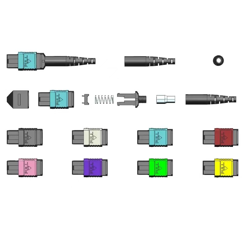
| Connector geometry | MPO rows, width, pins and key | Controls physical compatibility | IEC interface and drawing |
| Patching model | Direct, panel, cassette or harness | Changes connections and loss | Channel topology |
| Migration | Named future optic variants | Avoids speculative overbuild | Alternative BOM and trigger |
How to Control 800G fiber count planning in the Project
The controls below connect the drawing, sample, production lot and installed result. They are deliberately practical: each one produces a record that procurement, engineering and field teams can review later.
Freeze optics before trunks
Confirm the exact transceiver option on both ends. If procurement must start earlier, approve separate passive designs for each permitted optic rather than blending them into one assumption.
Map every lane
Show transmit, receive and unused positions through jumpers, trunks and modules. Include direction and viewing convention on connector-face diagrams.
Budget the chosen topology
Count all connections introduced by panels or cassettes and allocate acceptance margin to the complete channel. Direct and structured links should not share an unexplained loss limit.
Plan test access and spares
Confirm that test interfaces and reference cords support the selected MPO geometry. Stock the exact pin and key arrangement used by the approved channel.
Acceptance and Handover Checks
Agree the method and disposition before testing begins. A result without a defined record owner or failure action is difficult to use during shipment release or commissioning.
| Check | Method | Record | Failure action |
|---|---|---|---|
| Optics approval | Verify module codes | Signed equipment list | Stop ambiguous order |
| Lane map | Review connector faces | Controlled drawing | Correct missing lanes |
| Pilot channel | Assemble full path | Measured pilot | Revise topology |
| Per-fibre test | Measure all active positions | Result file | Quarantine failed lane |
| Spare audit | Match pins, key and count | Inventory record | Procure correct spare |
Standards and Evidence to Put Behind the Purchase Order
This IEC publication covers the two-row, 16-fibre-wide MPO interface. See IEC 61754-7-3 16-fibre-wide MPO interface.
This IEC procedure addresses attenuation, polarity and length testing for installed MPO-terminated cabling. See IEC 61280-4-5 MPO cabling test procedure.
The 2024 edition specifies inspection and testing of installed optical-fibre cabling. See ISO/IEC 14763-3:2024 optical cabling testing.
Planning summary
Plan 800G cabling from the exact optical interface outward. A documented lane map and alternate bill of materials are safer than assuming one MPO count will fit every 800G module.
- Approve exact optic variants
- Draw every lane
- Name MPO geometry and pins
- Test the complete pilot channel
- Stock matching spares
For a project-specific quotation, review Fenxi’s MPO/MTP data center cabling, LC connector range, MPO adapter panel guide, and 800G to 1.6T migration guide. Send the destination market, connector interfaces, fibre type, cable construction, quantities, drawing revision and required test records. The response can then separate standard catalogue options from items that need confirmation or custom tooling.