
Centralized splitting places the split at one main distribution point, while cascaded splitting divides it across two or more stages. Choose by service-area geometry, fibre availability, power budget, growth sequence and fault-isolation method rather than splitter count alone.
Centralized designs can simplify port mapping and changes at the hub. Cascaded designs may move capacity closer to subscribers and stage investment, but they introduce additional locations and dependency between splitter stages. The comparison must use the same subscriber area and include every connector, splice and passive stage.

What Must Be Decided for centralized vs cascaded splitting?
Use the decision table to turn the topic into controlled purchase, design and acceptance inputs. Each row should be confirmed against the actual equipment, route and destination standard rather than copied from a generic catalogue.
| Decision area | What to specify | Why it matters | Evidence to retain |
|---|---|---|---|
| Service geography | Premise density and route lengths | Shapes splitter placement | GIS and route map |
| Power budget | All stages, connectors and fibre | Limits feasible cascade | Worst-case calculation |
| Growth model | Ports activated by phase | Affects stranded capacity | Build-out forecast |
| Operations | Test access and fault boundaries | Controls repair time | Troubleshooting procedure |
| Records | Stage and output relationships | Prevents ambiguous paths | Port database |
How to Control centralized vs cascaded splitting in the Project
The controls below connect the drawing, sample, production lot and installed result. They are deliberately practical: each one produces a record that procurement, engineering and field teams can review later.
Compare identical service areas
Model both architectures for the same premises and routes. Comparing a small centralized case with a larger cascaded case produces misleading fibre and cabinet totals.
Budget every passive event
Include each splitter stage, connector, splice and fibre length in the engineering budget. Keep design reserve explicit rather than hiding it in a nominal splitter value.
Plan fault isolation
State where technicians can connect test equipment and how they identify the affected first- or second-stage output. Cascading without records can widen the search area.
Model the growth sequence
Show when feeders, splitters and distribution fibres are installed and activated. Judge cost and capacity at each phase, not only at final build-out.

Acceptance and Handover Checks
Agree the method and disposition before testing begins. A result without a defined record owner or failure action is difficult to use during shipment release or commissioning.
| Check | Method | Record | Failure action |
|---|---|---|---|
| Route model | Verify premises and lengths | Common input dataset | Correct model |
| Loss budget | Review worst path | Approved calculation | Reduce split or events |
| Capacity | Map active and spare ports by phase | Growth table | Change staging |
| Fault trial | Trace a selected subscriber | Field procedure | Add access or labels |
| Records | Audit stage relationships | Database export | Correct missing mappings |
Standards and Evidence to Put Behind the Purchase Order
The 2025 paper describes GPON, XG(S)-PON, 50G-PON and coexistence references for access networks. See ITU broadband access technical paper.
The in-force 2024 recommendation defines bend-insensitive single-mode fibre categories and their application scope. See ITU-T G.657 bend-insensitive fibre recommendation.
Corning lists component, module and rack formats and identifies GR-1209/1221 qualification for its PLC splitter range. See Corning PLC splitter qualification reference.
Decision summary
The sound architecture is the one that remains traceable and within budget during each growth phase. Preserve the assumptions, route data and stage map used in the decision.
- Use one service-area dataset
- Calculate the worst path
- Map every splitter stage
- Test the fault-isolation workflow
- Review each build phase
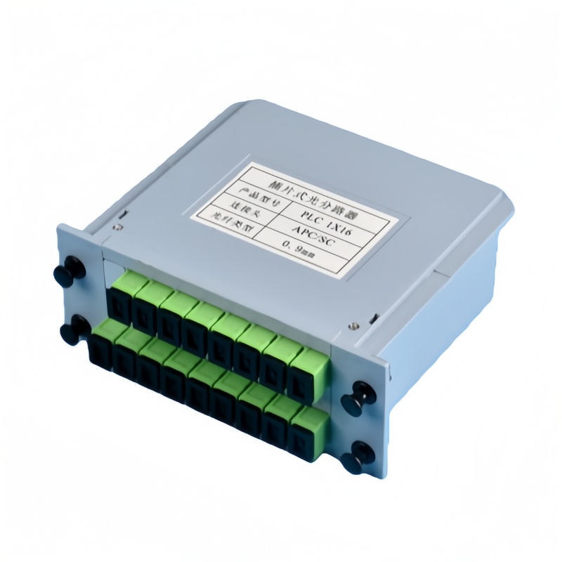
For a project-specific quotation, review Fenxi’s fiber optic splitter range, 1×16 SC APC PLC splitter, PLC and FBT splitter comparison, and PON power-budget planning guide. Send the destination market, connector interfaces, fibre type, cable construction, quantities, drawing revision and required test records. The response can then separate standard catalogue options from items that need confirmation or custom tooling.