
An 800G switch port and a 1.6T switch port may sit in the same rack, but that does not make their fiber channels interchangeable. The speed printed on the module is only the first decision. Buyers must match the PMD, optical lane count, connector format, key orientation, pinning, polish, fiber grade, channel loss and breakout map.
This distinction matters in 2026 because the two generations now overlap. IEEE 802.3df defines production 800G Ethernet interfaces based mainly on 100 Gb/s optical lanes. IEEE P802.3dj is developing 200 Gb/s-per-lane physical layers and 1.6 Tb/s Ethernet; its Draft 3.2 completed a second Standards Association recirculation ballot in August 2026, so it should still be cited as a draft rather than a finished standard (IEEE 802.3, 2026). At ECOC 2026, the Ethernet Alliance announced a multi-vendor demonstration spanning 400G, 800G and 1.6T, including 1.6T OSFP connectivity, 224G SerDes and link training. That is strong evidence of an operating ecosystem, but it is not permission to buy a generic “1.6T-ready” trunk.
The right migration plan starts with the installed cable plant, not the speed roadmap. A well-documented OS2 trunk may survive several switch generations. A new but poorly specified MPO assembly may fail on day one because it presents the wrong fiber positions. This guide shows how to audit what can stay, map new optics to passive components, set measurable acceptance criteria and phase the cutover without treating every rack as a greenfield build.
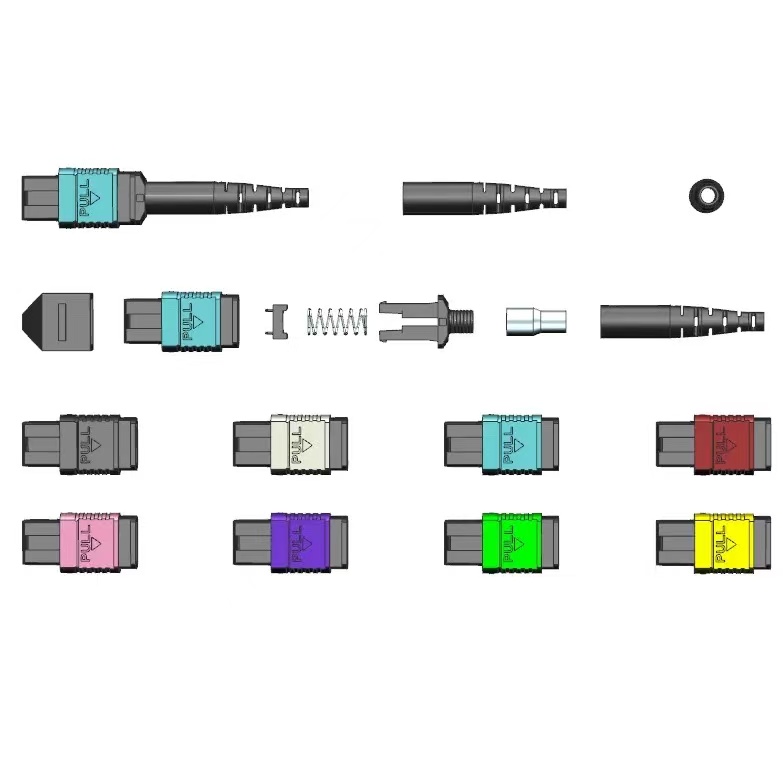
What Actually Changes Between 800G and 1.6T?
The central change is the move from 100 Gb/s optical lanes to 200 Gb/s optical lanes, not simply twice as many fibers. A production 800GBASE-SR8 or 800GBASE-DR8 channel carries eight transmit lanes and eight receive lanes. The resulting sixteen active fibers make MPO-16 a logical equipment interface. The emerging 1.6TBASE-DR8 family also uses eight lanes in each direction, but each optical lane carries 200 Gb/s. Fiber count can remain sixteen while the transmitter, receiver, FEC behavior and optical budget change.
This is why connector count cannot be inferred from aggregate speed. One 800G module may present a single MPO-16, another may present two MPO-12 receptacles for two four-lane optical groups, and a wavelength-multiplexed design may present duplex LC. Early 1.6T modules show the same variety: single MPO-16, dual MPO, or multiple duplex interfaces depending on the PMD and vendor implementation. The exact module data sheet is the design authority.
IEEE 802.3df covers 800GBASE-SR8 over eight pairs of multimode fiber to 100 m, 800GBASE-DR8 over eight pairs of single-mode fiber to 500 m, and 800GBASE-DR8-2 to 2 km. P802.3dj is defining 1.6T MAC and physical layers over copper and single-mode fiber using 200 Gb/s or greater per lane signaling. Until that amendment is approved, the procurement document should name the draft revision, module part number and vendor qualification requirement rather than claim final “IEEE 802.3dj compliance.”
| Interface case | Lane model | Medium and reach | Typical equipment presentation | Migration consequence |
|---|---|---|---|---|
| 800GBASE-SR8 | 8 Tx + 8 Rx at 100 Gb/s per lane | OM4/OM5, up to 100 m | MPO-16 UPC | Existing OM4 may remain for 800G, but it is not a default 1.6T path |
| 800GBASE-DR8 | 8 Tx + 8 Rx at 100 Gb/s per lane | OS2, up to 500 m | MPO-16 APC or module-specific parallel interface | OS2 route may be reusable if connector format, polarity, reflectance and loss pass |
| 800GBASE-DR8-2 | 8 Tx + 8 Rx at 100 Gb/s per lane | OS2, up to 2 km | Parallel single-mode interface | Check every connection because reflectance and total channel loss govern reuse |
| 1.6TBASE-DR8 family, draft | 8 Tx + 8 Rx at 200 Gb/s per lane | OS2; 500 m and 2 km objectives are in P802.3dj | MPO-16, dual MPO or vendor-specific presentation | Do not order by speed alone; lock the module and lane map before the cable |
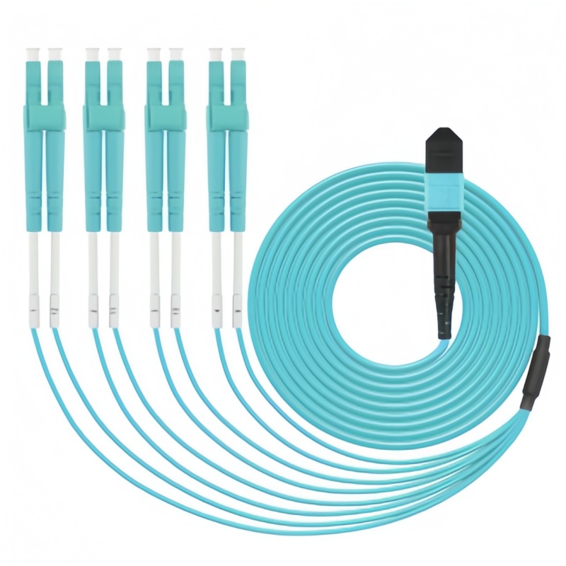
| 1.6T breakout | One port divided into 2 × 800G or 4 × 400G where supported | Module-dependent | Dual MPO, MPO-to-MPO fanout or MPO-to-LC transition | All three elements—parent optic, passive map and child optics—must share lane and FEC expectations |
The 2026 market signal is therefore coexistence, not immediate replacement. Ethernet Alliance demonstrations at OFC and ECOC placed 400G, 800G and 1.6T equipment in the same multi-vendor environment. For a buyer, the practical response is to qualify a mixed-generation bill of materials and preserve a known migration path, rather than buying every component at the newest stated speed.
Which Parts of the Installed Fiber Plant Can Stay?
Reuse is justified only when each passive element has a known interface, lane map and measured loss. The age of a trunk is less important than its fiber type, end presentation, routing condition and records. Start with a rack-to-rack route inventory, then examine the parts in order from the switch face to the far-end switch face.
An OS2 trunk is usually the strongest reuse candidate. G.652.D or bend-insensitive G.657.A1 single-mode fiber does not become obsolete when port speed changes; the optical module decides reach and wavelength behavior. The trunk can stay if its fibers are continuous, clean, correctly mapped and below the selected PMD’s loss and reflectance limits. A 12-fiber trunk, however, cannot magically become a sixteen-fiber parallel path. It can still serve a four-lane interface, a duplex wavelength-multiplexed link through a cassette, or one half of a dual-MPO design, but that choice must appear on the port map.
OM4 and OM5 require a stricter business case. They remain valid for standardized 800GBASE-SR8 at supported distances, yet the current P802.3dj scope for 1.6T emphasizes copper and single-mode fiber. If an AI row is likely to move to 1.6T during the cable plant’s service life, add OS2 backbone capacity rather than assuming a future multimode PMD. Keep OM4 for known 800G links and document its retirement trigger.
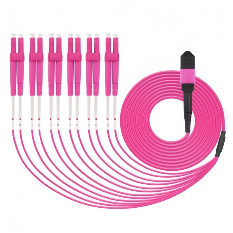
| Installed element | Evidence to collect | Reuse when | Replace or redesign when |
|---|---|---|---|
| OS2 trunk | Fiber count, length, IEC fiber grade, attenuation, splice/event map | Enough active fibers exist and installed loss/reflectance fit the new PMD | Unknown fiber routing, damaged events, too few fibers or no usable test baseline |
| OM4/OM5 trunk | Grade, actual length, connector count, 850 nm loss | Retained for a listed multimode 800G application within reach | Project expects 1.6T single-mode optics or length exceeds the selected PMD |
| MPO-12 assembly | Keying, row count, pins, polarity method, active fiber map | Selected module uses MPO-12, dual MPO-12, or an engineered cassette transition | Equipment requires direct MPO-16; the formats are not mechanically interchangeable |
| MPO-16 assembly | Offset-key interface, pins, APC/UPC, per-fiber loss | Both optics and panel adapters use the same MPO-16 interface and lane order | An endpoint uses MPO-12, different polish, or a vendor-specific pin arrangement |
| Cassette or breakout | Front/rear ports, internal map, component loss, serial number | Drawing matches the new parent and child ports and loss is budgeted | Internal mapping is undocumented or the added connection consumes margin |
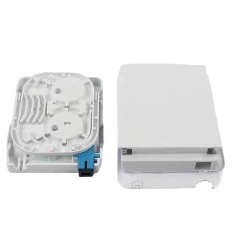
| ODF and pathway | Adapter type, module slots, bend clearance, tray fill, labels | New adapters/cassettes fit and routing preserves bend radius | Panel cannot accept MPO-16, rear space pinches trunks, or records cannot trace ports |
Do not ignore the frame. A reusable cable can still become unusable at a panel whose adapter footprint, cassette depth or rear manager cannot accept the new interface. The fiber ODF should have enough module space, front patching clearance and rear bend control for both the transition state and the final 1.6T layout. Likewise, an adapter is not a passive afterthought: its key orientation and mechanical interface decide whether a trunk can be presented correctly.
How Do MPO Format, Polish, Pinning and Polarity Control Compatibility?
A correct fiber count can still fail if the connector interface or lane order is wrong. MPO-12 and MPO-16 are deliberately different. The 16-fiber interface defined within the MPO family uses an offset-key arrangement that prevents accidental mating with the centered-key 12-fiber format. An adapter cannot convert the ferrule geometry; conversion requires a purpose-built assembly or cassette with a documented map.
Polish is the next gate. Multimode SR8 channels normally use flat or PC/UPC multifiber interfaces. Parallel single-mode DR links commonly use APC to reduce back reflection. Never mate APC to UPC, and never order “green MPO” as a substitute for a written polish specification: boot and housing colors are visual aids, not acceptance evidence. State APC or UPC on the purchase order and on the assembly label.
Pinning determines which ferrule supplies the alignment pins. A direct equipment patch cord commonly has an unpinned connector at the transceiver end because the module receptacle carries pins, while trunk-to-trunk and panel connections follow the selected design. The safe rule is not “male at one end, female at the other”; it is “draw every mated pair and show which side has pins.” Two pinned connectors cannot mate, and two unpinned connectors will not align correctly.
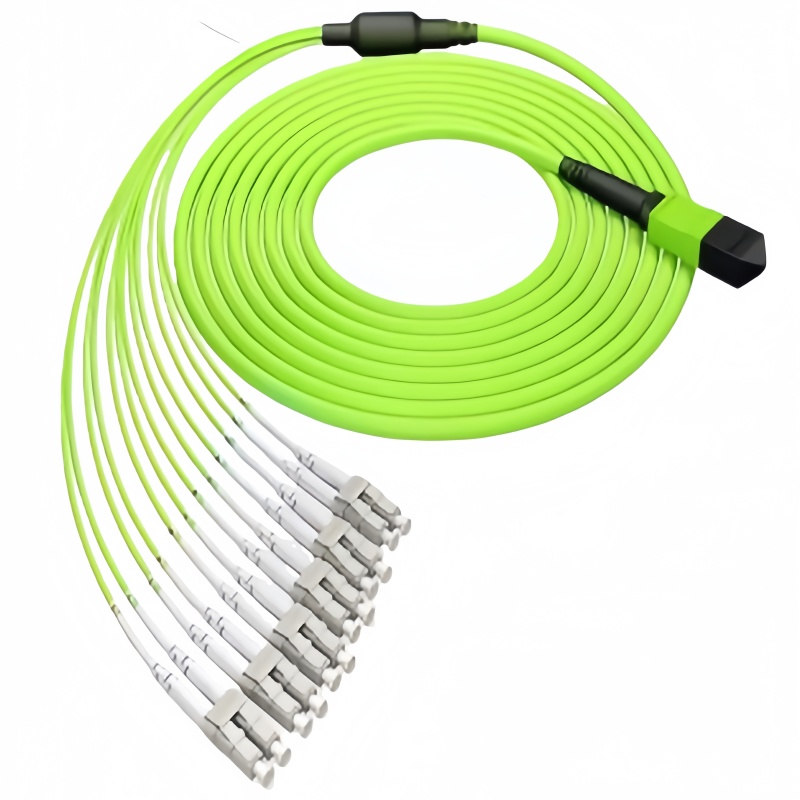
Polarity determines whether each transmit lane arrives at its intended receive lane. Method B is common for parallel optics because it reverses the fiber order end to end, but a generic Method B label is not enough for every breakout. A 1.6T-to-two-800G branch has to map parent lanes to the correct child module and port, and a 1.6T-to-four-400G branch adds another grouping decision. Use a position-by-position diagram. Our MPO polarity Method A, B and C guide explains the base methods; the migration drawing must add the actual module lane assignments.
The connector interface should reference TIA-604-5 (FOCIS 5) and IEC 61754-7, but standards compliance does not prove the requested map. In June 2026, TIA TR-42.11 opened work on TSB-5074, “Port Mapping Fundamentals for Structured Fiber Cross-Connect Architectures,” specifically to align active port arrangements with modular passive components, housings and slot assignments (TIA, 2026). That development reflects a real operational problem: as lane counts and breakout choices rise, port administration becomes part of physical-layer engineering.
How Should the Channel Loss Budget Be Recalculated?
The only valid pass limit is the maximum channel loss for the selected optical PMD, reduced by a deliberate engineering reserve. A component catalog value cannot replace the module’s channel specification. Start with the exact optic at each end, then model every mated pair, splice, cassette and meter of fiber in the installed route.
Use the basic equation:
Channel IL = fiber attenuation × length + sum of connector-pair losses + sum of splice losses.
Then add measurement uncertainty and an operator-defined reserve outside the calculated channel loss. The reserve covers aging, repeated mating, temperature and future patching; it is not free space for poor workmanship. On a short 100 m or 500 m data-center route, connector loss usually dominates fiber attenuation. Deleting one cassette or cross-connect can therefore recover more margin than changing the fiber grade.
Low-loss MPO assemblies are often purchased at a maximum of 0.35 dB per mated pair, while ultra-low-loss grades may be specified at 0.20 dB. Treat those figures as supplier acceptance values, not universal allowances from IEEE. If the module data sheet permits less, the module wins. If a channel contains three mated pairs at 0.35 dB, the connector allocation alone is 1.05 dB before fiber, splices, uncertainty or reserve. This arithmetic is why an apparently small patch-panel change can decide whether a 200 Gb/s-per-lane link passes.
Single-mode DR links need reflectance review as well as insertion loss. Fluke Networks notes that short-reach single-mode applications are more sensitive to connector reflectance and that permissible channel loss can depend on the number and reflectance class of connections. Use APC interfaces where the module specifies them, keep connection count within the PMD model, and characterize suspect events with an OTDR. The earlier fiber insertion-loss budget guide gives the component-by-component calculation method.
For component tests, reference IEC 61300-3-4 for attenuation and IEC 61300-3-6 for return loss. IEC 61300-3-35 defines end-face visual inspection criteria; standards can be obtained through the IEC Webstore. The project specification should identify the edition it adopts, the test wavelength, reference method, launch cords and whether results are required in both directions.
What Testing Proves the Plant Is Ready for Cutover?
A migration link is ready only after inspection, lane-map verification, optical certification and live traffic qualification all pass. Each test catches a different fault: total loss cannot detect crossed lanes, a correct map cannot detect contamination, and a clean ferrule cannot prove module interoperability.
Begin with an inspect-clean-inspect sequence on every connector before mating. MPO inspection must capture all active fibers and the guide-pin area; checking only one corner of the ferrule is not enough. IEC 61300-3-35 pass/fail images should be retained against the assembly serial number. The Fluke Networks fiber-inspection reference provides field guidance on inspection practice.
Next, test continuity and polarity position by position. For a direct MPO-16 channel, the report should identify all sixteen positions. For a breakout, it should identify the parent position and the child connector/port for every lane. Do not accept a single “polarity pass” line when the tester cannot export the map. The installed label, drawing and electronic test record must use the same port identifier.
Tier 1 optical loss testing measures the end-to-end channel. Test multimode at 850 nm and 1300 nm with an encircled-flux-compliant launch where required; test single-mode at 1310 nm and 1550 nm unless the selected PMD states otherwise. Compare every fiber with the tighter of the application limit and approved design budget. A passing average cannot hide one bad lane.
Tier 2 OTDR testing is strongly justified for new OS2 trunks, reused routes with unknown events, and short-reach single-mode channels where reflectance matters. Bidirectional analysis separates real event loss from directional measurement effects. It also records the location of splices, macro-bends and connector events for later fault isolation.
| Acceptance item | Method and reference | Required evidence | Release rule |
|---|---|---|---|
| End-face condition | Automated microscope; IEC 61300-3-35 | Image for each ferrule and all active fiber positions | Pass before mating; clean and reinspect after any fail |
| Continuity and polarity | MPO polarity tester or mapped light source | Parent-to-child lane map tied to port IDs | 100% of active Tx positions arrive at intended Rx positions |
| Insertion loss | OLTS; IEC 61300-3-4 component method and project channel method | Per-fiber result, wavelength, reference setup and tester calibration | Every lane is below both the approved design budget and PMD maximum |
| Return loss/reflectance | OTDR or return-loss meter; IEC 61300-3-6 | Per-event reflectance for single-mode routes where required | Event count and values fit the selected module’s channel model |
| Length and event map | OTDR, preferably bidirectional for acceptance | Route length, splices, connectors, bends and event locations | Reach is within the PMD limit and no unbudgeted event remains |
| Live interoperability | Traffic generator or production pilot under load | Module IDs, firmware, temperature, lane power, FEC and error log | No uncorrectable errors; corrected-error behavior meets vendor release criteria |
The production pilot should use the planned switch software, module firmware and cable build under operating temperature and load. Record per-lane optical power, temperature, FEC corrected codewords and link retraining. If the passive channel passes while errors rise, investigate modules, firmware and electrical signal integrity before replacing fiber.
Which Failure Modes Cause the Most Rework?
The most expensive failures are specification mismatches that stay hidden until optics arrive. They are rarely caused by the glass itself. Use the following diagnostic order so teams do not clean, repatch and replace good components while the real fault remains in the design record.
- Wrong physical interface. Confirm MPO-12 versus MPO-16, single-row versus multi-row ferrule, key orientation and APC versus UPC. Stop if any interface differs from the approved drawing.
- Wrong pin arrangement. Inspect both sides of every intended mate. Two pinned ends will not couple; two unpinned ends cannot align to specification. Check adapter style as part of the pair.
- Wrong polarity or breakout grouping. Trace each lane from parent port to child port. If an entire child link is dark, suspect grouping or cassette mapping before suspecting attenuation.
- Contaminated or damaged end face. Inspect before cleaning, use the correct MPO cleaner, inspect again, and quarantine ferrules with chips, scratches or guide-pin damage.
- Loss budget consumed by transitions. Count mated pairs and cassettes again. Temporary test adapters left in the final channel and undocumented cross-connects are common sources of extra loss.
- Bend or routing damage. Compare OTDR events with pathway changes. Tight rear-panel bends and crushed trunk bundles can affect only some fibers, creating a misleading partial failure.
- Module or platform mismatch. Verify coding, supported PMD, breakout mode, FEC and firmware at both ends. A mechanically correct channel does not guarantee optical or protocol interoperability.
Separate the passive and active fault domains during troubleshooting. First prove the fiber channel with calibrated test equipment. Then connect the approved modules and inspect digital diagnostics. If the passive channel passes but traffic fails, preserve that evidence and move the investigation to modules, switch configuration, firmware and thermal behavior.
What Must Appear in the RFQ and Supplier Evidence Pack?
A usable RFQ describes a complete channel and its proof, not a cable name. Send the supplier a port schedule and rack drawing before requesting the bill of materials. The schedule should name the switch, port, transceiver part number, PMD, far-end device, route length and migration stage. Without those fields, “800G/1.6T MPO cable” remains ambiguous.
| RFQ field | What the buyer must state | What the supplier must return |
|---|---|---|
| Endpoint definition | Switch/NIC model, port ID, optic part number and PMD at both ends | Compatibility matrix and any platform qualification limits |
| Optical interface | MPO-12, MPO-16, dual MPO, LC; APC/UPC; active fiber positions | Connector drawing, IEC/TIA interface reference and end-face photo sample |
| Pinning and polarity | Pin expectation at each mate, Method A/B/C where applicable, breakout grouping | Position-by-position lane map with key orientation and adapter type |
| Cable construction | OS2/OM4/OM5, fiber count, length tolerance, jacket rating, pulling method | Cross-section, outer diameter, bend limits, tensile limit and compliance data |
| Optical performance | Maximum component IL/RL, channel budget, test wavelengths and reserve policy | Per-fiber factory results, test method, uncertainty and lot distribution |
| Panel and cassette | Rack unit, module slots, front/rear presentation, labeling scheme | Loaded layout, internal map, loss allocation and rear-clearance drawing |
| Identification | Site/rack/port IDs, A/B path, serial format, barcode or QR requirement | Label proof and electronic port list before production |
| Packaging | Dust caps, individual bagging, spool or figure-eight coil, pulling eye if required | Pack list tied to route IDs and handling instructions |
| Quality and schedule | First-article quantity, inspection hold point, production lots and delivery sequence | Sample date, approval gate, production lead time, split-shipment dates and warranty |
| Acceptance package | Required OLTS, OTDR, inspection, polarity and live-pilot record formats | PDF plus CSV/raw files tied to assembly serial and final port ID |
Require a first article for every distinct connector/polarity build. Review the sample, label, lane map and electronic report together. For long trunks, request protective pulling eyes and controlled coiling; for equipment cords, require port-sequenced bags so installers do not sort near-identical assemblies on the data-hall floor.
Break lead time into drawing approval, first article, component allocation, production, testing and transport. Ask whether ferrules, specialty adapters and cable are allocated, and state whether partial shipment by row or pod is acceptable. The MPO/MTP patch-cord range can be built against this port map rather than a speed-only description.
800G to 1.6T Upgrade Roadmap
The lowest-risk route is audit first, prepare the passive layer second, pilot third and cut over in repeatable groups. This sequence lets 800G continue carrying production traffic while the 1.6T ecosystem and the P802.3dj text mature.
Stage 1: Freeze the current-state port map
Inventory ports, optics, cords, cassettes, trunks, adapters and far-end ports. Record MPO format, keying, pinning, polish, fiber positions, media, length and test-report location. Mark each item verified, inferred or unknown; unknown plant is not reusable until tested.
Stage 2: Prepare generation-neutral passive routes
Keep verified OS2, add fibers where counts are short, and use modular panels that can present MPO-16, dual MPO or LC through replaceable cassettes. Maintain separate A and B routes. Size rear managers for old and new jumpers during transition. Keep working OM4 on known 800G SR links and document its retirement trigger.
Stage 3: Approve one end-to-end pilot per build
For each PMD and breakout, qualify the production switch, firmware, modules, patching, trunk, panels and far-end device. Complete inspection, polarity, OLTS, OTDR where required, and loaded traffic testing. Freeze drawings and part numbers only after the pilot passes.
Stage 4: Deploy by row, pod or fabric plane
Move a bounded group, confirm telemetry, then repeat. Keep rollback cords and previous port assignments until observation closes. If breakout is the bridge, label the 1.6T parent and every 800G/400G child.
Stage 5: Retire temporary transitions and preserve evidence
When native 1.6T endpoints replace child links, remove unused transitions, recertify changed channels, update DCIM/AIM records and store reports with the serial-number list. Retain spares by exact build, not merely by length.
Send the current port map, selected 800G and 1.6T module data sheets, rack elevations and route lengths to Changzhou Fenxi Optoelectronics Technology Co., Ltd. We can return a matched passive BOM covering MPO trunks, breakout assemblies, adapters and ODF modules, with polarity drawings and per-fiber test records for approval before production.