
An adapter that mates correctly can still fail the installation if its flange, latch, screw spacing or panel-thickness range does not match the enclosure. Freeze the adapter footprint and the panel cutout on one controlled drawing, then approve a populated panel sample before releasing production tooling.
Panel-fit problems are expensive because they often appear after painted metalwork has been punched and shipped. Catalogue names such as simplex, duplex, quad, square flange and trapezoid flange are not dimensional definitions. The buyer should treat the adapter, cutout, fastener, panel finish and technician access as one mechanical interface.
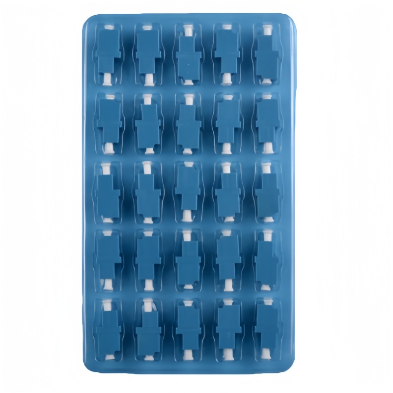
What Must Be Decided for fiber adapter panel cutout?
Use the decision table to turn the topic into controlled purchase, design and acceptance inputs. Each row should be confirmed against the actual equipment, route and destination standard rather than copied from a generic catalogue.
| Decision area | What to specify | Why it matters | Evidence to retain |
|---|---|---|---|
| Cutout geometry | Dimensioned hole shape, corner radii and orientation | Controls seating and rotation | Approved adapter and panel drawings |
| Mounting style | Clip, screw, flange and fastener specification | Changes assembly time and service access | First-article installation photographs |
| Panel thickness | Permitted metal thickness after coating | Affects latch engagement and movement | Thickness range and coating callout |
| Port pitch | Horizontal and vertical centre spacing | Determines latch and cleaning-tool access | Fully populated panel trial |
| Revision control | Adapter body and panel-tool revision | Prevents silent fit changes | Change notice and retained sample |
How to Control fiber adapter panel cutout in the Project
The controls below connect the drawing, sample, production lot and installed result. They are deliberately practical: each one produces a record that procurement, engineering and field teams can review later.
Dimension from datums
Use common datums for the cutout, fasteners and port centres. Avoid dimension chains that accumulate tolerance across a long panel and leave the last adapter row out of position.
Include the surface finish
Powder coat, paint and plating reduce available clearance. State whether dimensions apply before or after finish and inspect burrs or coating build-up around latching surfaces.
Populate the worst-case area
Build the densest corner or full row with production adapters. Verify connector mating, latch release, inspection-probe access and cable bend path rather than checking an empty opening with a gauge.
Control substitutions
Two adapters sold under the same family name may use different flange or latch geometry. Require drawing comparison and first-article approval before a supplier changes the body or mould source.
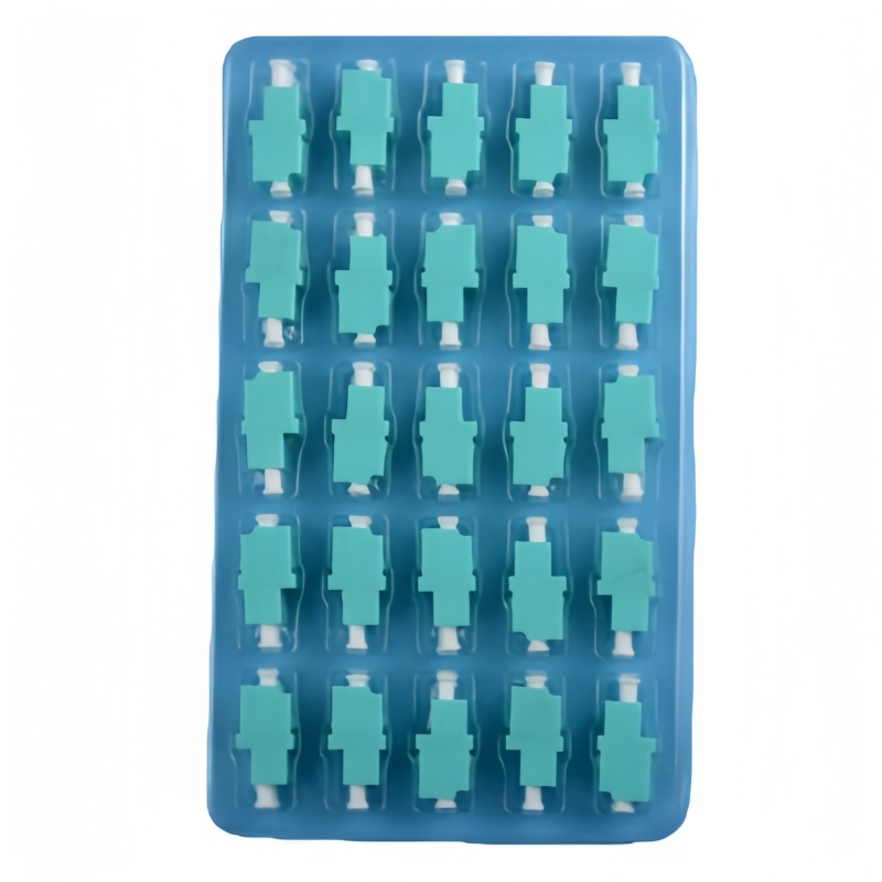
Acceptance and Handover Checks
Agree the method and disposition before testing begins. A result without a defined record owner or failure action is difficult to use during shipment release or commissioning.
| Check | Method | Record | Failure action |
|---|---|---|---|
| Cutout size | Measure finished openings from drawing datums | Dimensional report | Hold panel lot and review tooling |
| Adapter retention | Install and apply agreed handling check | Fit record and photographs | Reject loose or distorted positions |
| Adjacent access | Mate and release plugs in a full row | Technician access sign-off | Revise pitch or adapter style |
| Tool access | Use inspection and cleaning tools | Work instruction trial | Change layout before production |
| Appearance | Inspect burrs, coating and labels | First-article checklist | Rework finish before assembly |
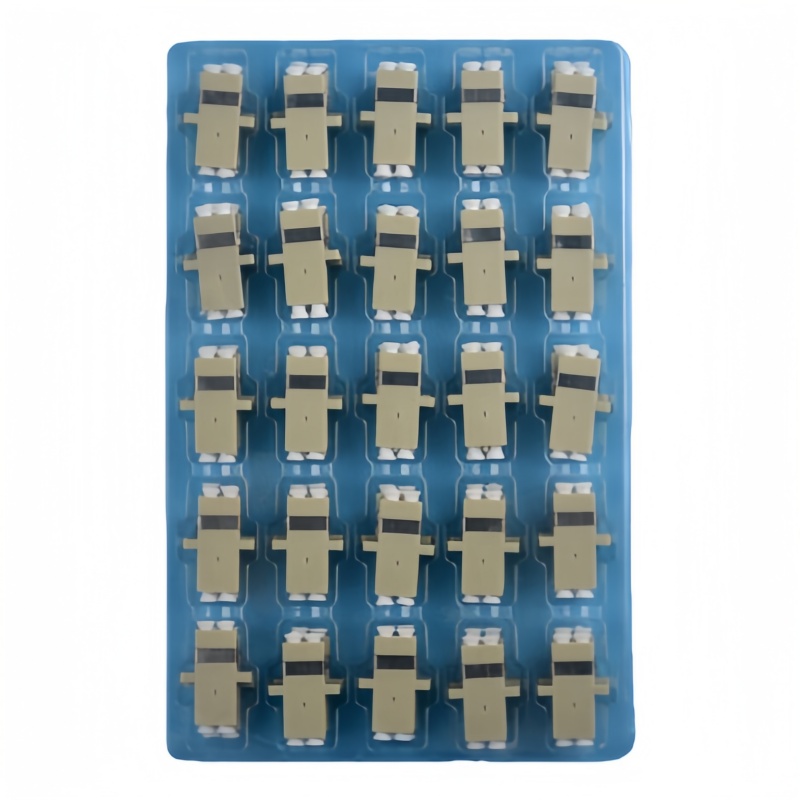
Standards and Evidence to Put Behind the Purchase Order
The current consolidated SC-family interface specification includes mounted-adapter cutout and ferrule compression-force references. See IEC 61754-4 SC interface standard.
This IEC publication defines the standard interface dimensions for the LC connector family. See IEC 61754-20 LC interface standard.
The 2026 edition evaluates optical and mechanical degradation through repeated mating cycles and adds updated cleaning criteria and severity levels. See IEC 61300-2-2:2026 mating-durability test.
Engineering checklist
Approve the mechanical interface with real adapters in finished panels. A shared drawing, populated sample and change-notification rule remove most cutout disputes before they reach installation.
- Link adapter and panel drawing revisions
- State finished panel thickness and coating
- Verify full-row service access
- Retain an approved first article
- Require reapproval after tooling or adapter-body changes
For a project-specific quotation, review Fenxi’s fiber optic adapter range, LC UPC duplex adapter, SC APC single-mode adapter, and fiber adapter selection guide. Send the destination market, connector interfaces, fibre type, cable construction, quantities, drawing revision and required test records. The response can then separate standard catalogue options from items that need confirmation or custom tooling.