
An MPO link can pass every insertion-loss and return-loss measurement and still refuse to negotiate. The connector seats, the end face inspects clean, the light source reads power at the far end, and the switch port stays down. On parallel-optics builds that usually means one thing: the fiber map is wrong. Polarity decides which transmit lane meets which receive lane, and a mismatch between trunk, adapter and module is the most common first-day failure on 40G, 100G and 400G channels.
Why Polarity Only Bites Once You Leave Duplex
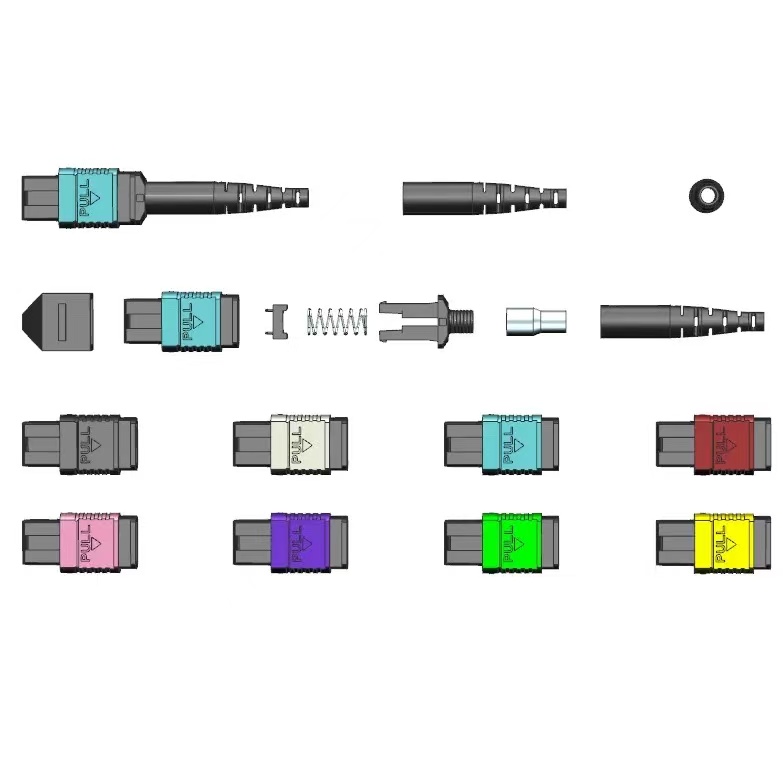
A duplex LC channel is easy to reason about: one transmit fiber, one receive fiber, and a patch cord that flips them. Multi-fiber connectors remove that simplicity. An MPO ferrule holds 8, 12, 16 or 24 fibers in a single row, each position numbered, and every trunk, adapter, module and jumper in the channel either preserves or changes that numbering. Three methods are standardised for doing so in TIA-568.3-D, the North American structured cabling standard, while the interface itself is defined in TIA-604-5 (FOCIS-5) and IEC 61754-7. The catch is that the ferrule, housing and boot look identical across all three methods. A Method A trunk and a Method B trunk are physically interchangeable and functionally incompatible, and nothing on the outside of the cable tells you which one is in the box. That is why MPO/MTP patch cords are specified by drawing rather than by part number.
Method A, B and C: What Each One Does to the Fiber Map
The three methods differ in one respect only – how a fiber that enters position N at one end leaves the other end – but that difference propagates through every downstream connection.
| Method | Trunk mapping (12F) | Trunk key orientation | Adapter type | Jumper required | Where it belongs |
|---|---|---|---|---|---|
| A – straight through | 1→1, 2→2 … 12→12 | key-up to key-down | Type A | One A-to-B duplex jumper at one end | Structured cabling; polarity is corrected inside the cassette or module |
| B – reversed | 1→12, 2→11 … 12→1 | key-up to key-up | Type B | A-to-A jumpers at both ends | Direct transceiver-to-transceiver parallel optics, 40G/100G/400G SR4, DR4, DR8 |
| C – pair swapped | 1↔2, 3↔4 … 11↔12 | key-up to key-down | Type A | A-to-A jumpers | Legacy duplex migration only; never for parallel optics |
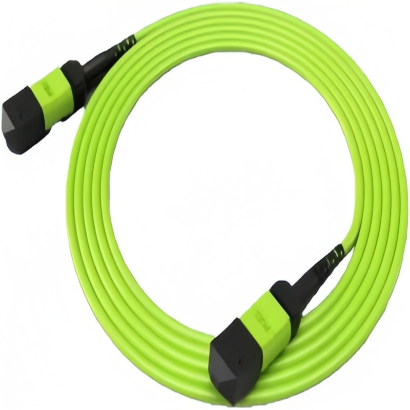
Method A keeps the sequence intact, so the polarity flip has to happen somewhere else in the channel, normally inside a cassette or module. Method B reverses the whole array with both ends key-up, which produces a clean transmit-to-receive alignment when two transceivers are patched directly. Method C swaps adjacent pairs and exists for duplex migration; it does not work for parallel optics, and a supplier who offers Method C for a 400G build is telling you something about how well the order was reviewed.
Matching the Method to Your Transceiver and Architecture
Two rules settle most of the ambiguity. If the channel contains a cassette or module, the module owns the polarity flip and the trunk stays straight – Method A. If two parallel-optics transceivers are patched together with no intermediate module, the array has to reverse – Method B. IEEE 802.3 settles the rest, because the lane mapping written into the Ethernet clauses is what the optics actually expect.
| Channel | Fibers used | Method | Why |
|---|---|---|---|
| 40GBASE-SR4 / 100GBASE-SR4 (QSFP+, QSFP28) | 8F, 4 Tx / 4 Rx | B | Lane mapping in IEEE 802.3 assumes a full array reversal between modules |
| 400GBASE-SR8 / 800GBASE-SR8 | 16F | B | OSFP and QSFP-DD direct patching needs Tx lanes aligned to Rx lanes |
| 400GBASE-DR4 / DR4+ single-mode | 8F | B | APSP lane order is fixed; APC polish rules out field key changes |
| MPO trunk into 6x LC duplex modules | 12F | A | The module owns the flip, so the trunk must stay straight |
| Leaf-spine trunk with modules at both ends | 12F or 24F | A | Simplest channel to migrate as port speeds change |
| Duplex migration over multi-fiber cabling | 12F | C | Only where pair-level swap is genuinely required |
Key Orientation, Gender and Adapter Type
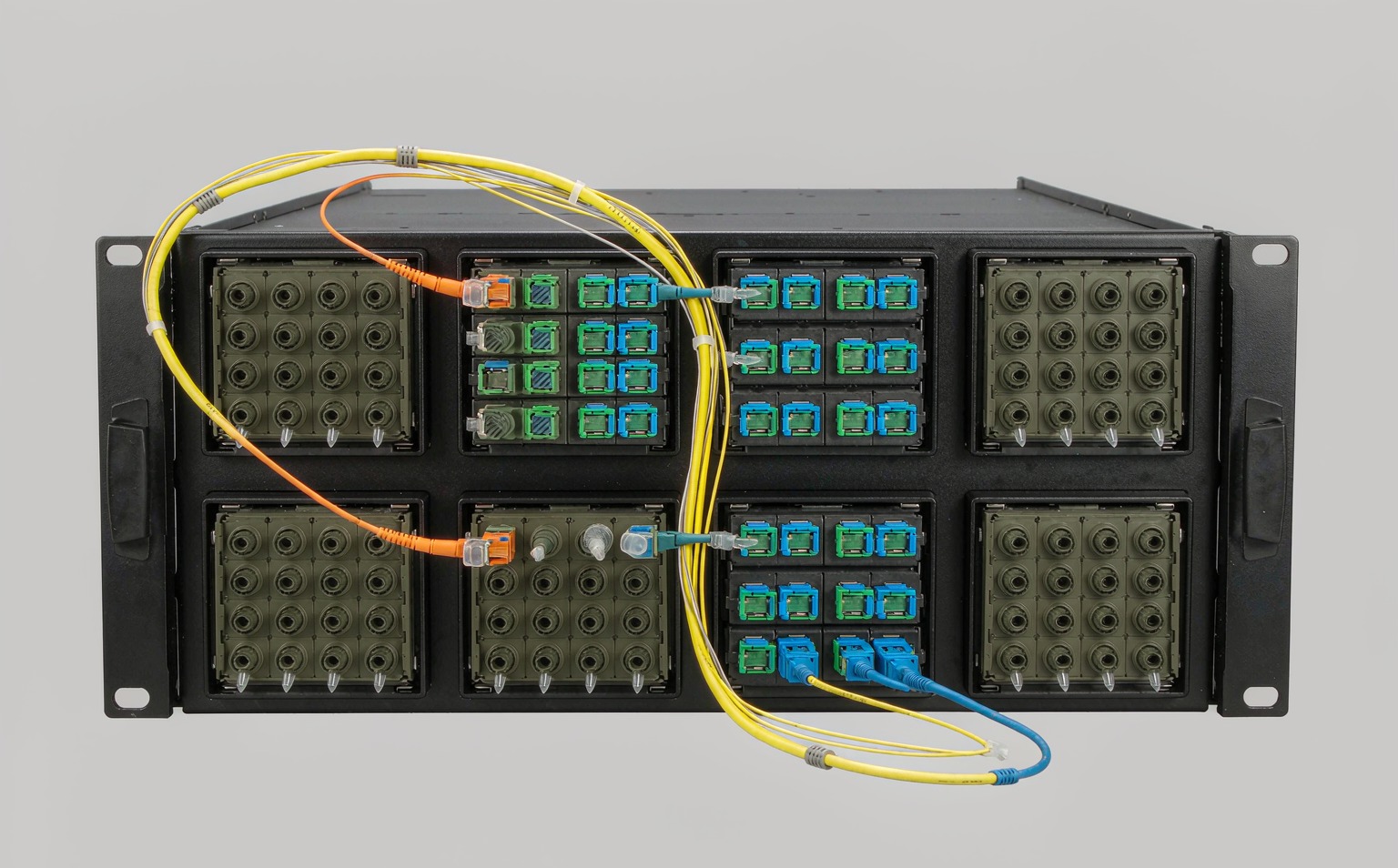
A polarity method only holds if the mechanical details agree with it. Key orientation comes first: a key-up to key-down adapter and a key-up to key-up adapter steer the fiber order in opposite directions, so the adapter has to be selected together with the trunk, never afterwards. Gender comes second. An MPO interface has one pinned side and one unpinned side, and two pinned ends or two unpinned ends will not align at all. Most QSFP and QSFP-DD ports are female, so a jumper patched straight into a transceiver needs a male end, while trunks are usually male at both ends and land in female module ports. Gender errors are the most frequent reason a delivered trunk is returned, and they are visible before anything is powered up. Third is polish. A flat UPC end face must never be mated to an 8-degree APC end face: the angled face crushes against the flat one, causing immediate loss and permanent ferrule damage. Where an APC trunk meets UPC equipment ports, the transition belongs in a hybrid module or a hybrid fiber optic adapter, not in a bare adapter. The FOA connector identification guide is a practical reference for reading the key and pin conventions on a delivered assembly.
Breakout, Cassette and Hybrid Deployments
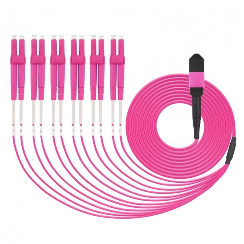
The riskiest channels are the mixed ones. A typical 100G-to-25G fan-out runs a 12-fiber Method A trunk into a module that presents six LC duplex ports; the module performs the pair mapping internally, so the trunk must not also reverse the array. Swap that module for a Method B trunk and the channel double-flips: transmit lands on transmit, the link stays dark, and the fault presents like a bad transceiver. The same trap catches teams that standardise in stages, because a Method A trunk bought for a cassette design cannot be reused when modules are later removed in favour of direct patching. Keep one method per channel from end to end, and record it on the drawing instead of in a technician’s memory. Field-changeable connectors from US Conec allow a key-up to key-down conversion in under a minute without exposing fiber ends, which is genuine insurance on multimode jumpers. The limit is polish: that rotation is only possible on a flat UPC ferrule. An 8-degree APC end face cannot be re-keyed without destroying the optical interface, so single-mode DR4, FR4 and long-reach channels must be specified correctly at order time. It is on multimode patch cords and OM4 or OM5 trunks that polarity recovery is still available after delivery.
What a Polarity Error Costs on Site
On a 96-fiber deployment, cable and connectors account for roughly a quarter of the installed cost; labour, test gear and project overhead take the rest. Polarity errors attack the expensive part. Tracing one mismatched trunk fiber by fiber with a visual fault locator and a power meter typically consumes two to four hours. A replacement pre-terminated assembly runs five to fifteen business days, and cut-to-length product is normally non-returnable. Every downstream link then needs re-verification, which on a 96-fiber spine can add eight to twelve technician hours. Fluke Networks documents the inspection and verification steps that catch these faults fastest, but inspection alone does not catch a mapping error. When a colocation go-live or a GPU cluster commissioning window depends on the channel, the schedule impact outweighs the hardware cost, and the whole failure is avoidable at the specification stage.
Documenting Polarity Before the Purchase Order
Two cables with the same fiber count, the same housing and the same boot colour are not interchangeable, and boot colour is not a reliable polarity indicator. The method belongs on the purchase order line rather than implied by a part number. Ask for the polarity drawing and the factory test report for every trunk and module before the order is released, confirm key orientation and gender at each end against that drawing, and state the verification method to be used at turn-up. On single-mode channels, treat APC as a hard constraint rather than a preference, because it fixes polish, module type and polarity options in one decision. At the cabinet end, the ODF and its modules should be specified in the same document as the trunk, so that one party owns the complete fiber map.
MPO Polarity Spec Checklist
Confirm every line below before the order is released. Anything left blank becomes a site visit.
| Spec line | What to state on the order |
|---|---|
| Polarity method | A, B or C written on the PO line, not inferred from a part number |
| Trunk key orientation | Key-up or key-down at end A and at end B |
| Gender | Pinned (male) or unpinned (female) at each end, matched to the mating port |
| Adapter type | Type A (key-up to key-down) or Type B (key-up to key-up) |
| Fiber count and map | 8F, 12F or 16F with the position map required by the transceiver |
| Jumpers | A-to-A or A-to-B duplex, quantity and length per end |
| Polish | UPC or APC, consistent across every element of the channel |
| Modules | Cassette or module wiring diagram supplied with the quotation |
| Documentation | Polarity drawing and factory test report before release |
| Turn-up test | Visual fault locator trace or MPO power meter, recorded per channel |
A channel that survives turn-up is one where polarity was decided once, in writing, before anyone opened a box.