
A splice tray is the part of a fiber network that nobody photographs and everybody blames. When a cabinet is opened two years after handover and the fibers are crossed, pinched, or held under a cover that will not sit flat, the cause is usually a tray that was ordered by fiber count alone. For FTTH, telecom, and data center projects the specification has to line up on five points at once: host enclosure fit, splice method, protector sleeve size, routing space, and material rating. This guide walks through each of them, then closes with an RFQ data sheet you can send straight to a supplier.
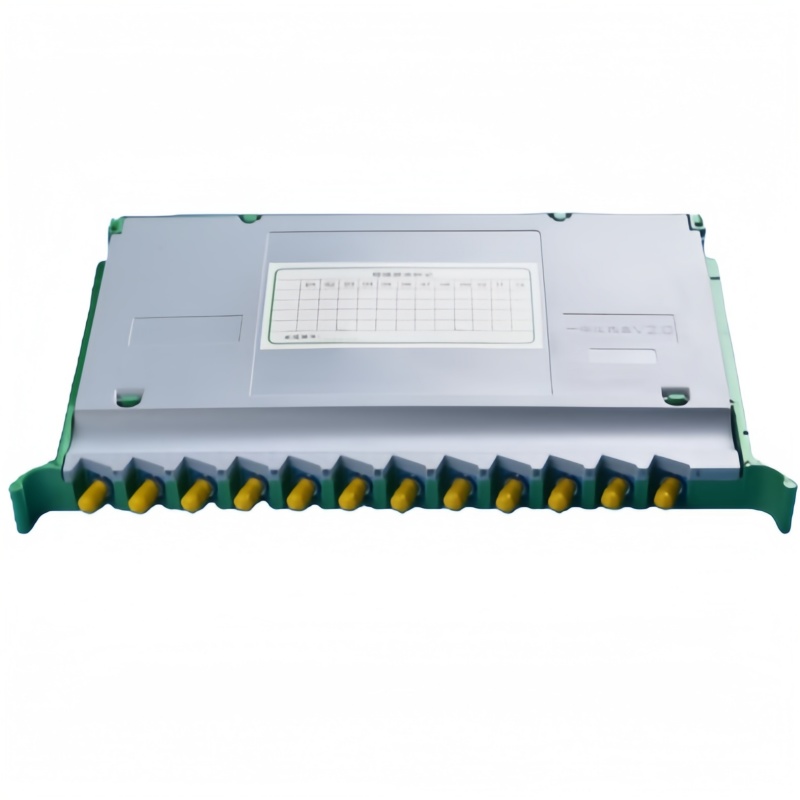
What a Splice Tray Actually Has to Do
A tray sits inside another product, so it inherits two jobs. The first is mechanical: it holds finished splices so that vibration, temperature cycling, and re-entry do not transfer stress to bare fiber. The second is optical housekeeping: it keeps every fiber above its minimum bend radius from the cable entry point to the adapter or pigtail exit.
That is why capacity printed on a datasheet rarely settles a purchase. A 24-core tray with a fixed single-layer holder, 12 mm of internal height, and no slack area will not accept 24 splices built on heat-shrink sleeves, and it may not accept 24 splices on short sleeves either once the technician has to route past the hinge. Nominal fiber count is only a starting filter; holder layout, sleeve channel, and usable routing area decide real working capacity. Read a supplier’s fiber optic splice tray range on those terms.
Tray Formats and Where Each One Belongs
Most trays on the market fall into five formats. Each is built around a different host, and mixing them up is the most common sourcing error we see from first-time buyers.
| Format | Typical capacity | Host equipment | Re-entry style |
|---|---|---|---|
| Standalone tray | 12 or 24 splices | Wall box, terminal box, splice closure | Lift-off or hinged cover |
| Stacked tray set | 12–24 splices per tray | Dome and inline closures | Hinged stack, flip up to reach lower levels |
| ODF splice module / cassette | 12, 24, or 48 splices | 19 in ODF frame, wall ODF | Slide-out on mounting rail |
| Rack-mount splice panel | 24 single or 288 ribbon splices per 1U | Data center and central office racks | Individually removable trays |
| DIN-rail industrial cassette | 12–24 splices | IP65 cabinets | Snap-off cover |
Two details separate a workable tray from a frustrating one. Removable trays let a splicer work at a bench instead of balancing over a rack, and separating the incoming loose tube from the outgoing pigtails stops the two bundles competing for one channel. Both cost little at the factory and save hours in the field.
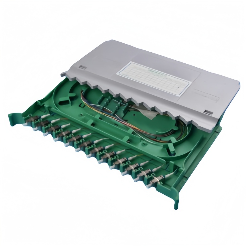
Capacity, Splice Method, and the Numbers to Quote
Quote three numbers to your supplier, not one: working splices, reserve splices, and total fibers entering the tray. Reserve capacity is not padding. Networks that start with 12 live fibers on a 24-core tray are following normal practice, because the second activation phase usually arrives long before the cabinet reaches end of life.
Four combinations cover most projects. An FTTH distribution point with 48 fibers is normally built as four 12-splice trays on 40 mm sleeves, leaving one spare level free. A 144-fiber feeder uses six 24-splice trays. Metro duct and data center work shifts to ribbon mass fusion, where one 12-fiber ribbon takes a single holder slot, so a tray rated at 288 splices in 1U is in fact holding 24 ribbons. If single fusion and ribbon splicing will share an enclosure, order configurable holders rather than a fixed single-layer layout.
Splice Protectors and Holder Fit
The protector is the sleeve that covers the fused joint, and its finished length is what the tray holder is designed around. It is the most overlooked line on a tray datasheet. Connector-side interfaces are covered by the ITU-T L.36 connector recommendation, but splice protection geometry is usually left to the tray drawing.
| Protector type | Finished length | Outside diameter | Notes for tray selection |
|---|---|---|---|
| Heat-shrink, single fiber | 60 mm | 2.6–3.0 mm | Standard for buried and outdoor work; needs the longest holder |
| Heat-shrink, single fiber | 40 mm | 2.4–2.6 mm | Most common indoor choice; matches most 24-core trays |
| Micro / thin sleeve | 25–30 mm | 1.5–2.0 mm | High-density 48-core cassettes; tighter bend control needed |
| Mechanical splice body | Varies by brand | 3–5 mm | Confirm body dimensions before ordering holders |
A 60 mm sleeve is roughly 50 percent longer than a 40 mm sleeve. On a fixed 24-slot holder with 41 mm spacing, that difference alone drops working capacity to 12 or 16 splices. Ask for the capacity that applies to your sleeve length and splice method, and get it stated on the quotation.
Bend Radius, Slack Storage, and Routing Rules
Single-mode fiber is normally installed with a minimum bend radius of 30 mm, multimode with at least 15 mm. Bend-insensitive G.657 tolerates tighter curves than G.652, but the tray is the wrong place to test that tolerance, because trays are opened and re-stacked far more often than buried cable.
- Keep at least 1.0–1.5 m of slack per fiber inside the enclosure, arranged in loops rather than folded runs.
- Use a storage radius of 40 mm or more for slack coils; straight channels across the tray should respect 30 mm.
- Route incoming cable fibers and outgoing pigtails in separate channels, so one re-splice does not disturb the other bundle.
- Anchor the cable and its strength member at the entry point, so pull force never reaches the splice holder.
- Reserve a label field on every tray and every adapter position; unlabeled trays are the main cause of long fault-finding times.
Material, Flame Rating, and Where the Tray Will Live
Flame-retardant ABS rated UL94 V-0 is the default for indoor trays, and it is what you should ask for by name. Polycarbonate appears where higher impact strength is needed, and metal trays or aluminium covers show up in outdoor, industrial, and high-temperature locations. Powder-coated steel is typical for rack-mount panels, with the tray bodies in ABS.
Operating temperature tells you which material to accept: −40 °C to +75 °C suits most outdoor enclosures, while indoor data center trays are usually rated 0 °C to +70 °C. Where the enclosure sees direct sun, UV-stabilised material and a UV-resistant cover matter more than a few extra degrees of range. In coastal or industrial areas, stainless steel fasteners are worth the small premium over plated steel.
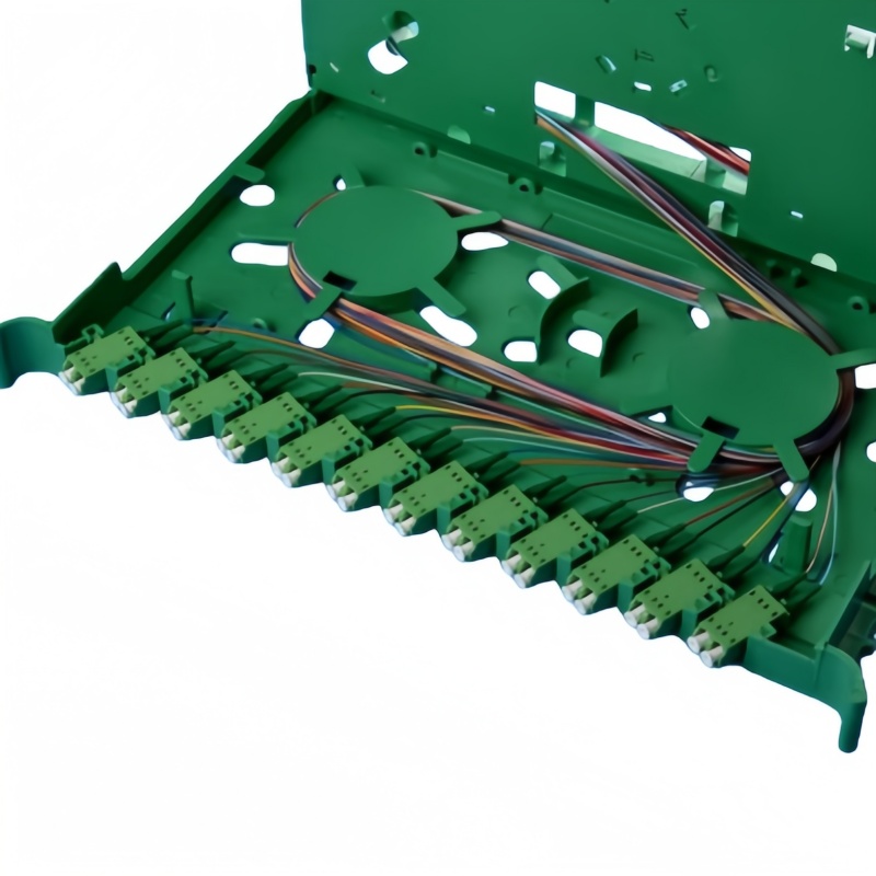
Fitting the Tray to the Host Enclosure
Start from the host, not the tray. Take the internal drawing of the closure, terminal box, or ODF and note four dimensions: available footprint, tray bracket spacing, usable internal height, and the swing clearance needed to open or slide each level. Frame-level sizing is covered in more detail in this guide to ODF capacity planning.
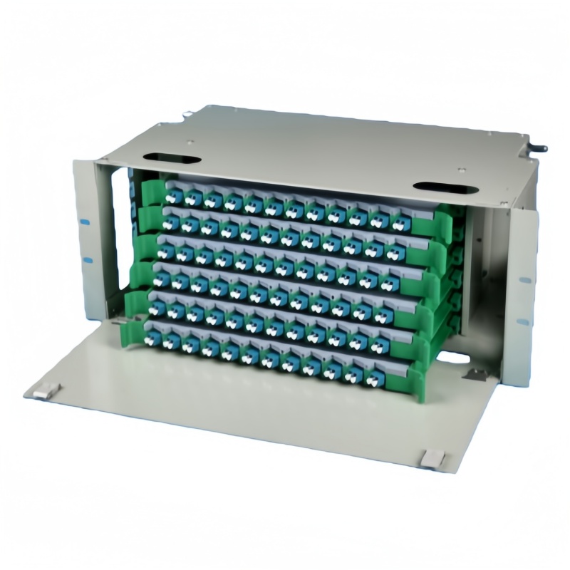
Inside a 19 in ODF distribution frame, a splice module slides on a mounting rail and shares the chassis with adapter panels, so the rail type has to match the frame. Inside a dome closure the limit is stacking height: eight 24-core trays need roughly 200 mm of usable depth once hinges and covers are counted. Inside a wall-mounted fiber termination box, the tray competes with a splitter module for the same space. When a 1×8 or 1×16 PLC splitter shares an enclosure with splices, plan the tray layout first, because splitter pigtails consume the same routing channels as the incoming cable.
Loss and Inspection Targets to Write Into the Contract
Splice quality is measured, not assumed. For single fusion on single-mode fiber, a mean splice loss of 0.10 dB with a maximum of 0.30 dB is a realistic acceptance figure, and it matches the per-component values used in link budgeting. The FOA loss budget reference and the Fluke Networks loss budget guide both work from that same set of numbers.
- Fusion splice, single-mode: ≤ 0.30 dB, mean ≤ 0.10 dB, verified by bidirectional OTDR or LTS on pigtails.
- Connector, single-mode UPC: ≤ 0.30 dB with return loss ≥ 50 dB, measured per IEC 61300 test methods.
- Connector, single-mode APC: ≤ 0.30 dB with return loss ≥ 60 dB.
- End-face condition: no scratches in the core zone, checked with an automatic inspection probe.
- Tray re-entry: no measurable loss change after five open and close cycles.
Cabling standards such as ANSI/TIA-568.3-D set the component limits behind those figures. Keep the re-entry line: a tray that meets its factory target but shifts fiber each time a technician lifts the cover fails in service, and the cost arrives as repeated truck rolls rather than a warranty claim.
RFQ Data Sheet: What to Ask a Splice Tray Supplier
Send these twelve lines with your enquiry. Answers in writing keep the technical comparison honest and stop a low quote from being translated into a thinner tray later.
| # | RFQ line item | Answer to obtain |
|---|---|---|
| 1 | Host equipment model | Closure, terminal box, ODF frame, or rack model, with internal drawing |
| 2 | Working and reserve splices | Live count plus growth margin for the next activation phase |
| 3 | Splice method | Single fusion, ribbon mass fusion, or mechanical |
| 4 | Protector sleeve | Finished length and diameter, or the exact sleeve part number |
| 5 | Capacity by splice method | Published capacity restated for your sleeve and holder configuration |
| 6 | Tray dimensions | Length, width, height, hinge position, stacking count |
| 7 | Material and flame rating | Tray, holder, and cover material with UL94 rating |
| 8 | Operating temperature | Range matched to the deployment climate |
| 9 | Bend radius control | Minimum radius features and slack storage capacity |
| 10 | Cover and access | Latch type, tool requirements, cycles tested |
| 11 | Test documentation | Batch test report, material record, RoHS statement |
| 12 | Accessories | Mounting brackets, labels, cable ties, spare covers |
Buyers who compare trays on these twelve lines usually find that the price spread tracks holder design and material grade rather than fiber count. A tray that fits the host, matches the sleeve, and survives repeated re-entry costs less across a ten-year network life, even when the unit price is higher. Fenxi supplies splice trays, ODF frames, termination boxes, and PLC splitters as a coordinated set, so the tray footprint and internal clearances already match the enclosure it ships with.