
Specifying LC connectivity for a dense fiber build usually starts with one question from the network owner: how many duplex ports can we fit in the rack space we have left? The connector footprint answers only part of that, because ferrule tolerance, adapter style, polarity scheme, and the panel architecture behind the ports decide whether a 1U shelf carries 24 traceable channels or 144 ports nobody wants to touch during a maintenance window. A wrong connector call is cheap on the purchase order and expensive in year two.
What “High Density” Means at the Connector Level
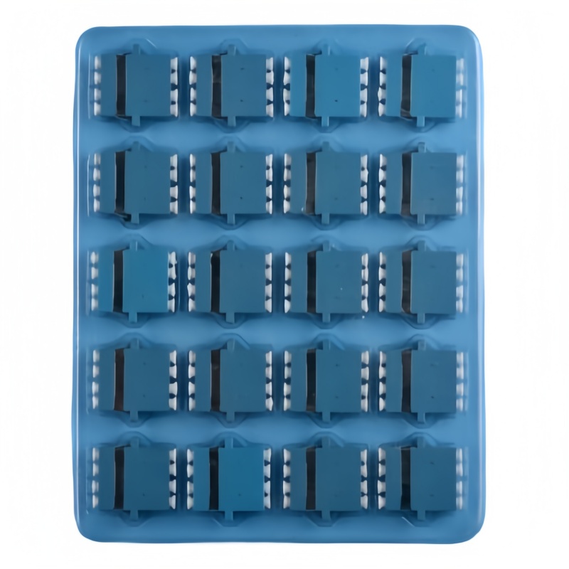
The LC (Lucent Connector) uses a 1.25 mm ferrule, half the diameter of the 2.5 mm ferrule used by SC, FC, and ST. That one dimension is why a 1U panel holding 24 SC simplex ports holds 48 LC duplex ports, or 96 fibers, in the same metalwork. Intermateability is defined by IEC 61754-7 for the interface and TIA-604-5 (FOCIS 5) in North America, so a compliant LC from one vendor mates with a compliant LC from another.
What differs between suppliers sits behind that interface: ferrule concentricity, endface geometry, latch spring force, and the boot diameter chosen for 0.9 mm, 2.0 mm, or 3.0 mm cable. Three mechanical details decide whether a dense build stays serviceable. The duplex clip holds the pair aligned but widens the profile behind the panel. Adapter retention decides whether the connector stays seated when a cord is side-loaded. And access matters: push-pull tabs and short boots are the difference between a 30-second change and unplugging three neighbours to reach the middle row of a 144-port shelf.
Port Density and Rack-Unit Math
Density planning works backwards from the transceiver count, not forwards from the panel catalogue. Count active ports, add the growth factor the network owner will admit to, then add the spare ratio maintenance actually consumes. The table shows what each interface delivers in a standard 19-inch 1U shelf.
| Interface | Ferrule diameter | Ports per 1U panel | Fibers per 1U | Typical fit |
|---|---|---|---|---|
| SC simplex | 2.5 mm | 24 | 24 | Low-count ODF, single-circuit patching |
| SC duplex | 2.5 mm | 12 duplex pairs | 24 | Legacy telecom frames |
| LC duplex | 1.25 mm | 48 duplex ports | 96 | Data center MDA and HDA, enterprise backbone |
| LC quad adapter | 1.25 mm | 72 to 96 | 144 to 192 | High-count ODF, hyperscale halls |
| MPO-12 cassette | Array | 8 to 12 cassettes | 96 to 144 | Trunk-to-LC breakout |
| MPO-16 / MPO-24 | Array | 4 to 8 cassettes | 64 to 192 | 400G spine links, parallel optics |
A worked example: a leaf-spine pod with 48 switch ports per leaf, dual-homed, needs 96 fibers at the top of rack and 96 more at the MDA cross-connect. Two LC duplex panels in the rack and four at the cross-connect cover it. The same count in SC duplex consumes four times the rack units. Once fiber counts pass 500 per rack, MPO cassettes take the top of rack and LC takes the patching layer, the split our MPO/MTP patch cord range is built for.
LC Variant Selection for Dense Builds
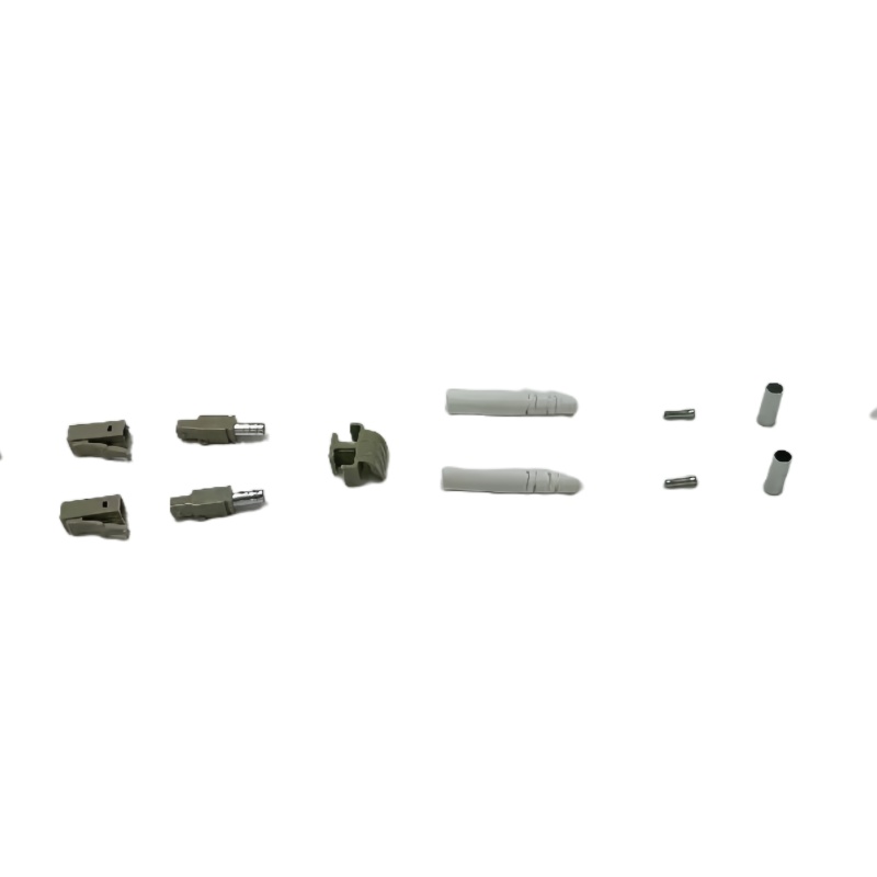
The LC family has moved well past the plain duplex connector. Each variant solves a constraint and carries one of its own.
| Variant | Constraint it solves | Typical deployment | What to watch |
|---|---|---|---|
| Standard LC duplex, 2.0 / 3.0 mm | General cross-connects | Patch panels, switch ports | Clip height and side-stack clearance |
| Uniboot LC, 2 fibers on 1 jacket | Halves cord bulk behind panels | Dense patching, airflow-critical aisles | Polarity can be flipped during jacket swap |
| LC quad adapter | Four ports in one adapter footprint | 144-port 1U shelves, high-count ODF | Finger access, pull-tab length |
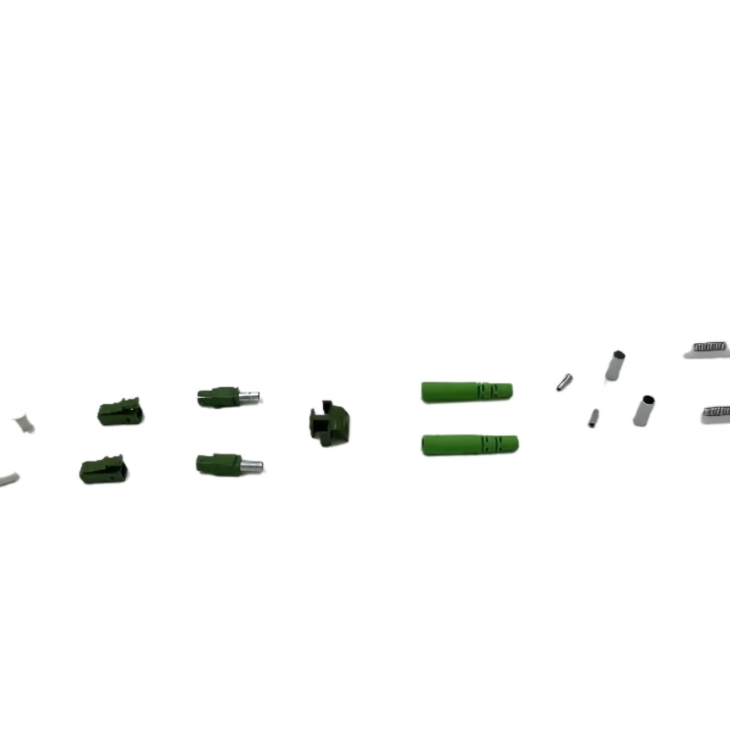
| LC APC | Return loss above 60 dB | PON, RFoG, analog video overlay | Never mate with UPC endfaces |
| SC to LC hybrid | Migration in existing frames | Legacy frame to new panel transition | Label both ends and the adapter |
| LC armored, UPC or APC | Crush and rodent protection | FTTA drops, industrial and outdoor runs | Bend radius at the cable entry |
UPC or APC follows service type. UPC is the default for Ethernet, where return loss above 50 dB keeps a 100G link comfortable. APC’s 8-degree angled endface pushes return loss past 60 dB, which is what PON splitters, RF video overlay, and high-split DOCSIS need. Never mate them: an APC ferrule against a UPC ferrule leaves a physical gap that ruins insertion loss and damages the endface. If a frame carries both, mark the polish on the adapter housing and the panel label.
For buyers specifying LC connectors across several sites, standardising the boot diameter is worth more than shaving a cent off the unit price: one boot size means one spare-parts bin and one set of cleaning tools in every technician’s bag.
Panel, Cassette, and ODF Planning
Panels come in three architectures, and the right one depends on how often the plant changes. Fixed panels are cheapest per port and fastest to install when fiber counts are stable. Modular LGX cassettes cost more upfront but let a team add 12 or 24 ports at a time without powering down neighbours, and they accept either MPO rear connectors or spliced pigtails. Sliding-drawer frames expose the rear splice trays, which matters in a central office where a technician cannot reach behind a live frame.
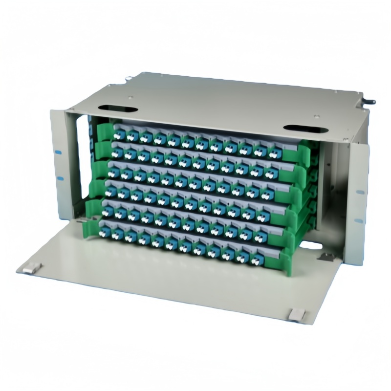
The frame behind the panel deserves equal attention. A 144-core LC ODF holds six splice trays at 24 fibers each, and that ratio drives tray height, slack storage depth, and the achievable bend radius through the routing path. Single-mode G.657.A2 tolerates a tighter radius than legacy G.652.D, but no standard supports a kink. Plan routing so the tightest point on any path stays at or above ten times the cable outer diameter, and confirm the tray limit on the datasheet before the frame is bolted down. Our ODF distribution frames are built around six-tray capacity that matches a 144-port LC front end.
Polarity and Fiber Mapping in Duplex LC
Polarity is the most common reason a link tests clean on one end and dead on the other. For duplex LC the convention is simple: on a transceiver, position A transmits and position B receives, so a straight A-to-B cord between two transceivers delivers two-way traffic. Trouble arrives from three directions: uniboot cords reversed during a jacket swap, MPO-to-LC breakout cords built to a polarity method (A, B, or C) that does not match the panel behind them, and panels assembled without a documented fiber map.
Write the map down before installation: which adapter position carries which fiber, which end is A and which is B, and which polarity method the breakout follows. A one-page map saves an hour of OTDR work per incident, and it is the first document a new technician reaches for when a channel goes dark at 2 a.m.
Insertion Loss, Return Loss, and Test Limits
Buyers should hold suppliers to published, testable numbers rather than a catalogue headline. Connector performance in a dense build is governed by endface geometry and cleanliness as much as ferrule quality, and the limits come from published standards.
| Parameter | Governing standard | Typical limit | Test method |
|---|---|---|---|
| Insertion loss, mated pair | IEC 61753-1 Grade B, TIA-568.3-D | Grade B 0.25 dB; commercial 0.35 dB | Light source and power meter, IEC 61300-3-4 |
| Return loss, UPC single-mode | GR-326-CORE, IEC 61753-1 | 50 dB or better | OCWR or OTDR, IEC 61300-3-6 |
| Return loss, APC single-mode | GR-326-CORE | 60 dB or better | OCWR or OTDR, IEC 61300-3-6 |
| Endface geometry | IEC 61755-3-1 | Apex offset 50 um or less | Interferometry |
| Mating durability | GR-326-CORE, GR-1435-CORE | 500 matings, change of 0.2 dB or less | IEC 61300-2-2 |
| Temperature cycling | GR-326-CORE | Change of 0.2 dB or less, -40 to +75 C | IEC 61300-2-22 |
| Endface cleanliness | IEC 61300-3-35 | No scratches in the core zone | Probe microscope at 200x or 400x |
A specification promising 0.2 dB without stating grade, wavelength, and test method is not a specification. Ask for the mated-pair figure at 1310 and 1550 nm for single-mode, 850 nm for multimode, measured to IEC 61300-3-4, then compare it against the loss budget for the longest link. That arithmetic is covered in our walkthrough of insertion loss budget calculation. Primary sources are worth reading directly: the TIA standards programme, the IEC webstore for 61754-7 and 61753-1, and the ITU-T G-series recommendations that govern the G.652 and G.657 fiber behind the connector. The FOA connector ID reference is a useful field aid for identification, and Fluke Networks’ loss budget reference covers test-side practice.
Deployment Pitfalls and Troubleshooting Matrix
Most dense-LC problems trace back to a small set of causes, nearly all of them caught before the link is energised. The matrix below matches the reported symptom to the cause worth checking first.
| Symptom | Likely cause | First action |
|---|---|---|
| Insertion loss above budget on a new link | Contaminated endface from a protective cap or handling | Inspect at 200x, clean with a one-click tool, re-measure |
| Intermittent loss on a live panel | Connector not fully latched, or side-load on a rigid duplex clip | Reseat, verify adapter retention, relieve cord tension |
| Channel dead after a uniboot cord swap | Polarity reversed during jacket work | Confirm A and B positions, re-terminate or re-route |
| Return loss fails on an analog service | UPC endface mated into an APC port | Verify polish markings on both ends before energising |
| Middle-row cords cannot be removed from a 144-port shelf | Boot diameter exceeds the quad adapter pitch | Switch to short-boot or uniboot cords for that row |
| Splice loss high inside an ODF | Bend radius or slack storage violation in the tray | Re-route, respect the tray minimum, re-test the tray |
| Fiber map unknown during a fault | No documented polarity method or port assignment | Trace with a VFL, then write the map before closing the frame |
Dense LC deployment rewards discipline at three points: the connector specification, the panel architecture, and the documentation. Get those right and a 144-port shelf is as manageable as a 12-port wall box. Send us your port counts, fiber type, polish requirement, and rack layout, and we will quote connectors, fiber optic adapters, patch cords, and frames against a single build sheet.