
Nobody buys a wavelength division system because they enjoy multiplexing. They buy it because one fiber pair has to carry more services than the duct to the tower will allow, and because trenching a new route costs more than every passive component in the rack combined. That pressure lands first on the parts treated as commodities: patch cords, adapters, connector interfaces, and distribution frames.
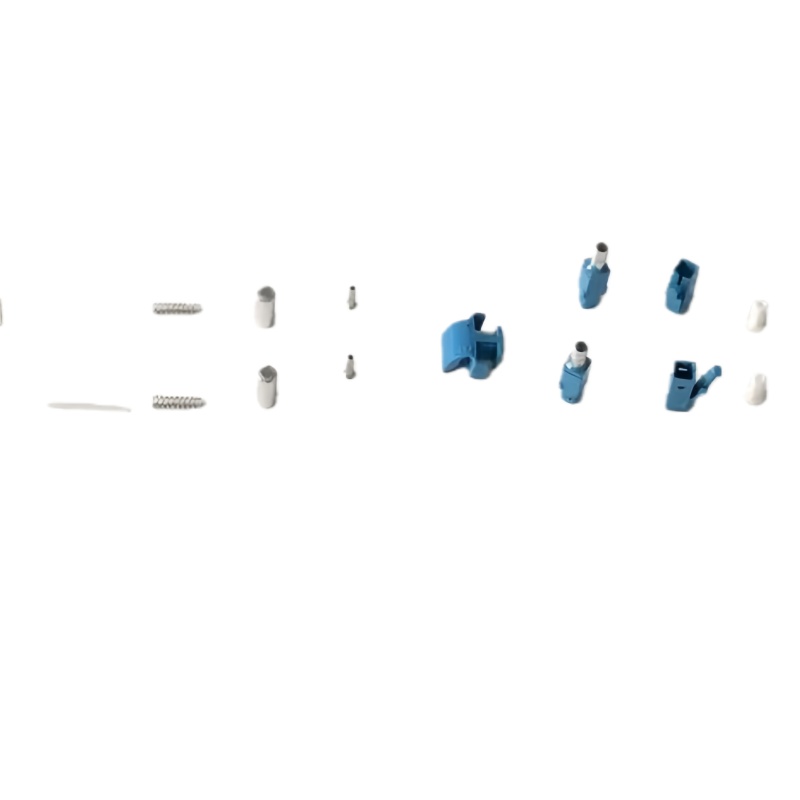
What CWDM and DWDM Change Below the Transceiver
CWDM spreads up to 18 channels across 1271-1611 nm on a 20 nm grid, wide enough that uncooled lasers hold wavelength without active temperature control. DWDM fits 40 channels on a 100 GHz grid, or 80 to 96 on 50 GHz, inside the C-band, and needs cooled, wavelength-locked optics. Both grids are standardized, so a compliant mux from one vendor lines up with a compliant transceiver from another: the dense grid is defined in ITU-T G.694.1 and the coarse grid in ITU-T G.694.2.
The difference usually gets filed as a transceiver question. It is equally a passive-layer question. A CWDM multiplexer passes a wide slice of spectrum per port and tolerates modest component variation and ordinary connector polish. A DWDM arrayed-waveguide grating has to separate channels sitting 0.8 nm apart, which turns small reflections and dirty endfaces into measurable penalties. Return loss a CWDM link shrugs off can cost a DWDM channel its margin. ITU-T G.671 is worth reading before a first DWDM order, because it frames optical components as parts of a transmission system rather than standalone hardware.
CWDM vs DWDM: Specification Comparison to Work From
| Parameter | CWDM | DWDM |
|---|---|---|
| Channel spacing | 20 nm | 100 GHz (0.8 nm) or 50 GHz (0.4 nm) |
| Grid reference | ITU-T G.694.2 | ITU-T G.694.1 |
| Wavelength band | 1271-1611 nm (O to L band) | C-band 1530-1565 nm, L-band extension |
| Channels per fiber pair | Up to 18 | 40 on 100 GHz, 80-96+ on 50 GHz |
| Per-channel rate in practice | 1G to 25G, direct detection | 100G to 800G, coherent |
| Reach without amplification | About 80 km | About 120 km |
| Reach with amplification | Not practical, spectrum too wide for one EDFA band | 2,000 km and beyond with EDFA or Raman |
| Filter technology | Thin-film filters, wide passband | AWG or TFF stacks, narrow passband |
| Connector return loss target | 45-50 dB, UPC normally acceptable | 55-60 dB, APC normally required |
| Dominant application | 5G fronthaul, metro access, campus | Data center interconnect, long haul, submarine |
Two rows drive most procurement arguments. The reflectance target is the one buyers under-specify, because a reflectance failure never appears on a simple insertion loss test. The reach-with-amplification row decides budget, because a DWDM build that eventually needs amplifiers carries EDFA cost, power, and cabinet space a CWDM build never sees. If the planning horizon is under three years and the span is under 40 km with 16 channels or fewer, CWDM is cheaper almost every time.
Where Each Grid Wins: Fronthaul, Metro Access, and Interconnect
| Deployment scenario | Typical span | Channel count | Grid that fits | Passive layer focus |
|---|---|---|---|---|
| Tower-top 5G fronthaul, AAU or RRU to DU | 0.5-10 km | 4-16 | Passive CWDM | Outdoor rated LC duplex jumpers, sealed adapters, pulling grip |
| Metro access ring | 10-40 km | 8-18 | CWDM | Rack-mount ODF, labeled patch fields, bend radius control |
| Campus or enterprise backbone | 1-10 km | 4-8 | CWDM | MPO backbone trunks, LC breakout cassettes, polarity discipline |
| Data center interconnect | 10-120 km | 16-96 | DWDM | High-density LC and MPO, low-loss trunks, APC endfaces |
| Long haul and submarine | 120 km to 2,000+ km | 40-96+ | Amplified DWDM | Splice trays, low reflectance connectors, tight splice loss control |
Read that table as a map of where the passive bill lands. Fronthaul and metro work is dominated by outdoor-rated assemblies and rack hardware, where the problem is weather, strain relief, and serviceability at height. Interconnect work is dominated by density and cleanliness, where the problem is fitting 96 channels into a shelf without bending anything past its minimum radius.
How the Passive Layer Sets WDM Link Margin
Start the arithmetic at the mux rather than the transceiver. A CWDM thin-film mux contributes 2.5 to 4 dB, a DWDM arrayed-waveguide grating 3 to 6 dB, and that arrives before a single connector is mated. Every LC or SC pair then costs roughly 0.15 to 0.30 dB in good condition, an ODF pass-through adds two more mating points, and a cord routed around a tight cabinet corner adds macro-bend loss no data sheet predicts well. A modest DWDM span with four mated pairs, one patch field, and two splices can consume 8 to 10 dB before fiber attenuation is counted. If the passive total lands above roughly 6 dB, re-plan the path instead of buying a higher-power module. The worked method sits in our insertion loss budget calculation guide.
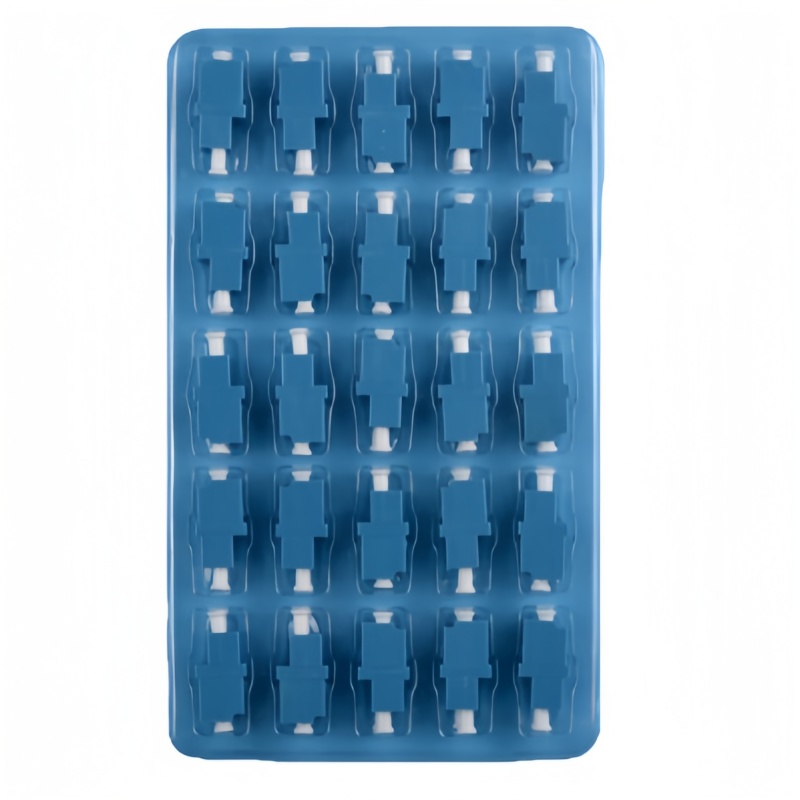
Connector Polish, Fiber Grade, and Cable Construction
Polish is the most consequential passive decision on a DWDM build, and it is usually made by whoever orders the jumpers last. UPC endfaces meet with a slight dome and reflect a fraction of the signal straight back into the transmitter. APC endfaces are ground at an eight degree angle so the reflection leaves the core at a wide angle and never returns. On a coarse grid that difference is a line item. On a dense grid it decides whether a channel stays inside its error budget as the path ages.
| Specification item | CWDM link | DWDM link | Why the difference exists |
|---|---|---|---|
| Connector polish | LC/UPC or SC/UPC commonly accepted | LC/APC or SC/APC preferred | An angled endface deflects reflections away from the source instead of back down the core |
| Return loss | 45-50 dB | 55-60 dB | A reflective pair can raise a DWDM channel error floor even when insertion loss looks fine |
| Trunk fiber grade | G.652.D with suppressed water peak | G.652.D, G.654 for long spans | Mid-grid CWDM channels cannot be carried on legacy high-water-peak fiber |
| Bend insensitive fiber | G.657.A1 at tight enclosures | G.657.A1 or A2 inside shelves | Macro-bend loss compounds across many turns in a dense panel |
| Jumper outer diameter | 2.0 mm for density, 3.0 mm for field handling | 2.0 mm in high-count shelves | Jacket diameter sets routing density and how much crush protection a cord carries |
| Endface cleanliness | Inspect and clean at every mate | Inspect and clean at every mate, no exceptions | Contamination a CWDM port ignores will scatter light inside a DWDM port |
The fiber matters nearly as much. Both grids assume single-mode propagation to ITU-T G.652, and on CWDM the mid-grid channels near 1383 nm are the ones that expose legacy cable with a high water peak, so ask for the cable certificate before assuming the full 18 channel plan will run. For jumpers, 2.0 mm jacketing buys routing density while 3.0 mm jacketing survives more field handling; the interface is the same LC connector or SC body either way, and our single mode fiber optic patch cord range covers both ends of a WDM port in UPC and APC.
MPO/MTP Trunking in Dense WDM Shelves
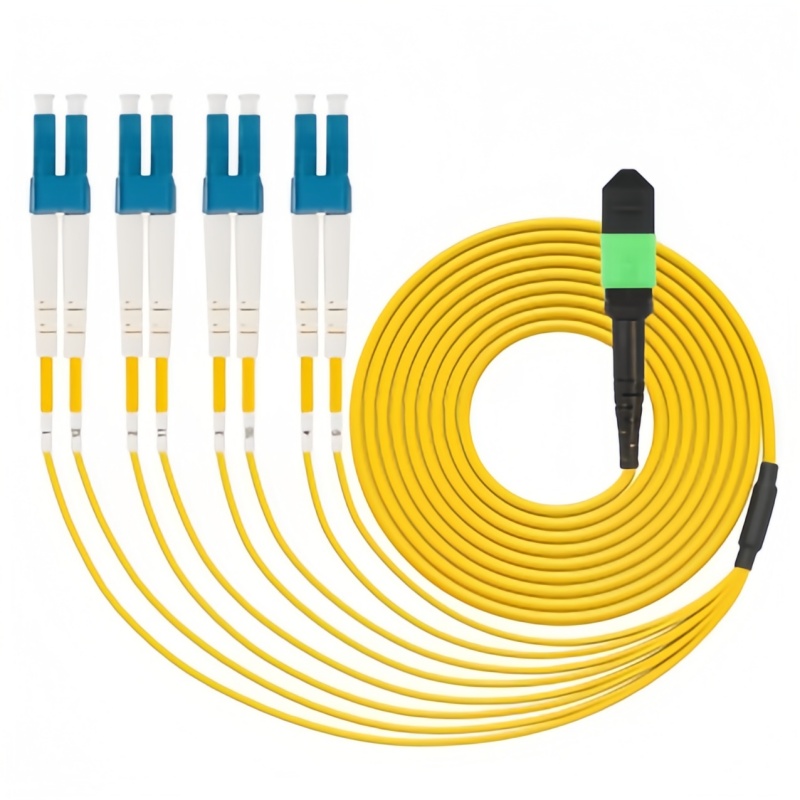
Once a shelf carries more than a few dozen WDM ports, individual duplex jumpers stop making sense. Single-mode MPO/MTP fiber optic patch cords carrying 8, 12, or 24 fibers run once from the frame to the shelf, and breakout cassettes fan them into LC pairs at the mux face. The trunk is installed once and never disturbed, so ports carrying live wavelengths are not re-mated during every capacity change. Two details decide whether that works. Use low-loss or elite-grade MPO connectors, because one MPO pair adds the loss of every fiber in it at once. Settle polarity before the first trunk is ordered, because key-up and key-down conventions differ between vendors and a reversed trunk surfaces at commissioning, not at the loading dock.
Distribution Frames and Wavelength Termination
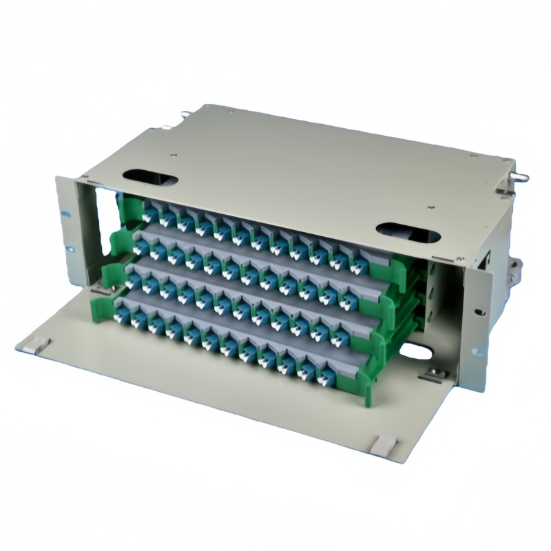
An ODF does more on a WDM network than tidy cable. It is where colored jumpers get re-graded, where a degraded cord is replaced without touching the mux, and where a technician can isolate one wavelength for testing while the rest keeps running. That works only if the frame is planned with slack. Budget roughly twice the port count you need at launch, protect the bend radius on every routing path, and label by wavelength rather than physical position, since positions shift with every upgrade. A frame sized for the ceiling of the channel plan costs little more than one sized for day-one traffic, and our ODF fiber optic distribution frame range runs from 12 to 144 cores.
Cleaning, Testing, and Budget Discipline
Most WDM faults reaching the field are not component failures. They are contaminated endfaces, a reversed pair, or an under-budgeted passive path. Inspect and clean every mating point before it goes together, including factory-terminated jumpers, because shipping dust is real. An insertion loss test at 1310 nm says little about a 1550 nm channel on an APC path, so measure per-channel loss and reflectance at the wavelength of interest and keep the numbers with the as-built record. Fluke Networks publishes a practical reference on assembling that budget, and it is worth standardizing your acceptance sheet on it.
Capacity Upgrade Roadmap: Three Phases
Plan the passive layer forward even if the transceivers only arrive in phase one. This sequence keeps each stage from invalidating the last.
Phase 1: day-one capacity, 0 to 12 months
- Deploy the grid matching today’s span and channel count.
- Order APC assemblies wherever a path may later carry dense-grid service.
- Install the frame at twice the launch port count with protected routing.
Phase 2: density growth, 12 to 30 months
- Add single-mode MPO/MTP trunks once duplex jumper count becomes a cabinet problem.
- Specify low-loss connectors on new trunks rather than mixing grades along one path.
- Re-baseline the as-built loss record channel by channel before adding amplifiers.
Phase 3: wavelength expansion, beyond 30 months
- Fill the remaining coarse-grid channels before considering a grid change on spans under 40 km.
- Re-terminate only the paths that need dense-grid reflectance.
- Recheck bend radius and crush protection on every route touched during the expansion.
Both grids are mature and widely available, so the decision is rarely about supply. It is about matching the grid to the span and then letting the passive layer carry the load it was specified for. Buyers who get that order right spend the next five years adding wavelengths instead of re-engineering cabinets.