
Most dead MPO channels get diagnosed as cable faults, yet the panel and the cassettes mounted in it decide polarity, gender, key orientation and usable lane count before any transceiver is powered. A 400G DR4 link that will not train is more often a mis-mapped cassette than a broken trunk. Fixing the fields below in the purchase order removes that class of failure, and the receipt checks at the end show how to confirm them before the panel goes into a live rack.
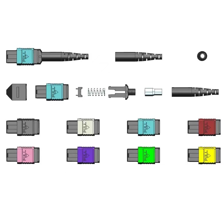
The Panel Sets the Channel Map, Not the Trunk
A duplex channel is one fiber pair. A parallel-optics channel is a bundle, and it runs through several transitions: transceiver to patch cord to adapter panel to trunk to adapter panel to patch cord to transceiver. Any of those transitions can flip the lane order, and the failure only appears when the link is tested end to end.
Polarity is the name for that lane order. The TIA defines three methods for 12-fiber MPO in TIA-568.3-D: Method A maps straight through, Method B reverses the whole array, and Method C swaps fibre pairs for breakout applications. For 12-fiber hardware the definitions are stable and vendor-neutral. For MPO-16 and MPO-24, no equivalent published language exists, so suppliers extend the 12-fiber logic on their own and the naming drifts. A “Type B” label on a 16-fiber assembly therefore tells you very little on its own.
Two rules keep this under control. First, buy one documented polarity method for the whole channel, and buy it from one source, so the trunk, the MPO/MTP patch cords and the cassettes are mapped together rather than assembled from three catalogues. Second, require a fibre lane map drawing with every quotation and file it with the PO. On 16-fiber and 24-fiber items the drawing is the specification; the label is only a nickname. Our note on 400G MPO trunk cable covers the cable side of the same decision.
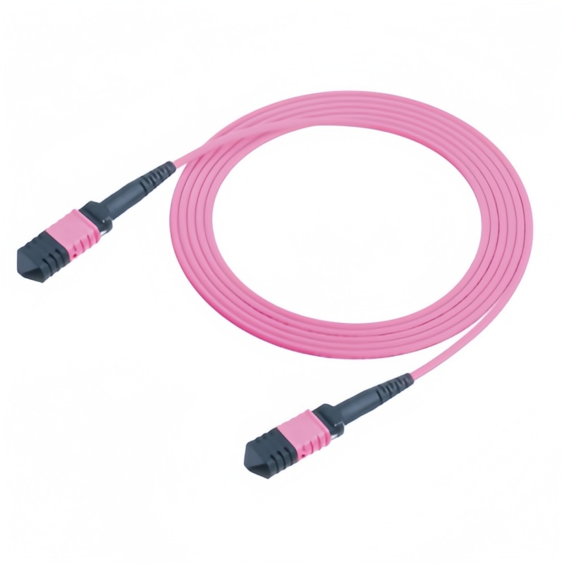
Fiber Count Comes Before Panel Style
“I need an MPO panel” is not a specification. Start from the optic, because the optic fixes the fiber count, and the fiber count fixes the module you can fit.
| Interface at the optic | Lanes used | Module to order | Note for the PO |
|---|---|---|---|
| MPO-8 (8F) | 4 TX + 4 RX | 8F or 12F cassette | 12F cassette leaves 4 fibres dark; fine for staged growth |
| MPO-12 (12F) | 4 or 8 TX + RX | 12F cassette | Most common legacy and 100G footprint |
| MPO-12 for single-mode DR4 | 8 of 12 | 12F APC cassette | APC polish is mandatory at 400G DR4; UPC will not mate |
| MPO-16 (16F) | 8 TX + 8 RX | 16F cassette | Ask for offset key and the 16-lane map |
| MPO-24 (24F) | 10 or 12 TX + RX | 24F cassette or direct coupler | Aggregation and backbone position, not edge |
| Dual MPO-12 or duplex LC | Varies | Hybrid cassette or LC panel | Same 800G family ships both; read the module part number |
400G is not a single optical interface. Under IEEE 802.3 the same data rate arrives as 400G-DR4 over MPO-12 single-mode with angled polish, as 400G-SR8 over MPO-16 multimode, and as 400G-FR4 or LR4 over duplex LC. Eight hundred gigabit modules split the same way, some using dual MPO-12 and some a single MPO-16. Before choosing a panel, record the exact transceiver part number and its interface table, because that table, not the data rate, decides the cassette. Coupler style follows polish, so the fiber optic adapters in the panel have to be ordered as APC or UPC to match the cassette behind them.
Polarity, Gender and Keying on One Line of the PO
These four fields cause most first-article rejections, and all four are decided before production, not on site.
| Field | Options | What to state |
|---|---|---|
| Polarity method | A, B, C | One method for the whole channel; supply the lane map for 16F and 24F |
| Gender | Male (pinned) or female (unpinned) | State the gender of the panel rear port and of the mating cable end, not “standard” |
| Key orientation | Key up, key down, offset key | Offset key is used by 800G optics; mixed plants need a panel that accepts both |
| Polish | UPC or APC | APC for single-mode parallel optics; never mate APC to UPC |
Gender is the field buyers most often leave to the supplier. Transceiver ports are normally pinned, so the assembly end that plugs into an optic must be unpinned, while a bulkhead joint between two assemblies needs one pinned end to align the ferrules. Because the two are independent of polarity, both have to be written down. Key orientation is the second trap: an MPO-16 built for 800G optics generally carries an offset key, while a legacy MPO-12 panel port is centred, and a mismatch is a physical block rather than a bad link. Where a plant mixes both, order cassettes with the correct keying per slot and label the slots at the panel face.
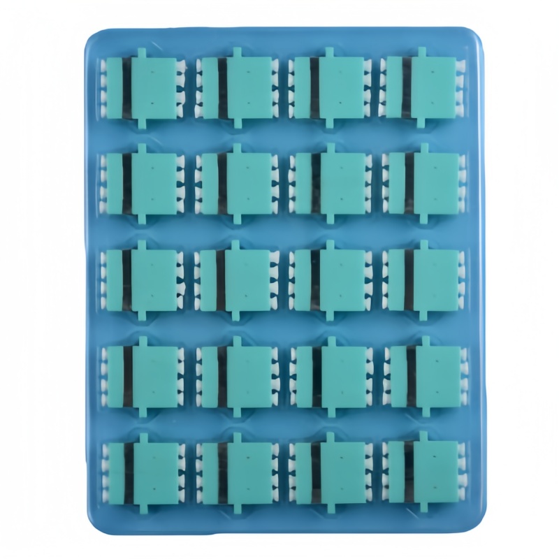
Density Math and the 12F to 16F Upgrade Path
Panel capacity is arithmetic, and it is worth doing before the chassis is chosen. A 1U modular housing typically takes four cassette positions. A 12-fibre cassette breaks one MPO-12 out to six LC duplex ports; a 16-fibre cassette breaks one MPO-16 out to eight. The same 1U housing therefore presents 24 duplex ports with 12F modules or 32 with 16F modules, with no change to the rack unit or the rear cabling. If the channel stays MPO to MPO with no breakout, direct coupler positions in the same chassis raise the port count further.
The upgrade path is the reason to buy a modular chassis rather than a fixed panel. Trunks land once at the rear and stay landed; a move from 12-fibre to 16-fibre optics is a front-face module swap in the affected slots, and the untouched slots keep running. That containment matters when a live zone is being migrated, and it keeps the ODF and distribution frame layer consistent with the spine plan. Mounting hardware, blanking plates and fiber optic accessories should be quoted with the chassis so that a partially populated 1U frame still closes and labels correctly.
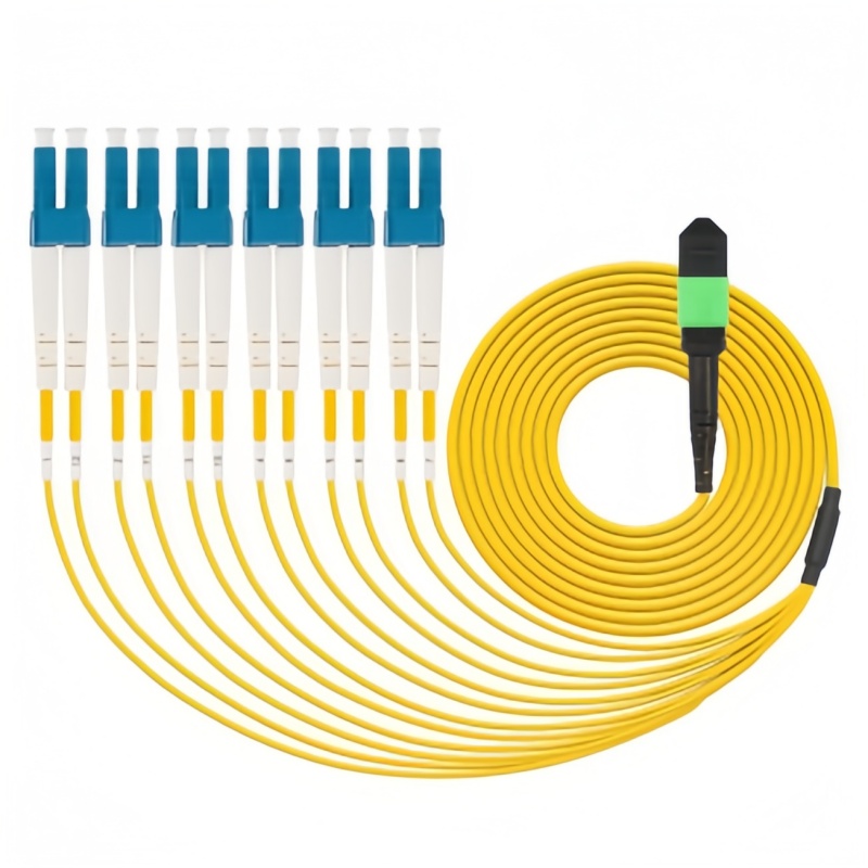
Acceptance Plan at Receipt
Test evidence is cheaper to specify than to argue about later. Put these items in the PO as deliverables, and reject a shipment that arrives with only a generic certificate.
| Check | Method | Accept | Document |
|---|---|---|---|
| Insertion loss, per mated pair | Light source and power meter, or MPO test set | Elite grade 0.35 dB max; standard grade 0.75 dB max | Per-port test file with serial numbers |
| Return loss | Same setup, APC and UPC separately | 60 dB min APC single-mode; 45 dB min UPC single-mode | Same file, per port |
| End-face condition | Inspection per IEC 61300-3-35 zones | Zone A and B pass, no scratch in Zone A | Image per port after cleaning |
| Lane map continuity | Continuity or OTDR trace through the channel | Matches the approved drawing fibre for fibre | Signed map against the drawing revision |
| Mating and retention | Sample pull and latch test | Connector 500 cycles min, cassette latches without tools | Sample record with batch code |
| Fiber and polish identity | Visual and label audit | Single-mode fibre matched to declared spec, APC and UPC not mixed | Label schedule |
Clean and inspect before every mate, and clean again after any failed test, because a single particle over one lane reads as a dark channel and sends teams into the wrong layer of the network. Field inspection practice is documented by Fluke Networks, and the cleaning step belongs in the receipt procedure rather than in the installation checklist. For single-mode link hardware, confirm the fibre grade against ITU-T G.652, and buy connector and interface performance against IEC 61754-7, IEC 61753-1 and GR-326 rather than against a datasheet summary; the IEC webstore is the place to confirm a current edition number before it goes into a contract.
A panel order that names the optic, the fibre count, the polarity method, the gender, the key orientation and the polish is a one-page document, and it is the difference between a channel that trains on the first attempt and a week of swapping parts. Send your transceiver list and channel drawing to Fenxi and we will return a panel, cassette and trunk bill of materials built around them.