
Choose the MPO fibre count from the active interface and lane map, then design trunks, cassettes and polarity around that map. Twelve fibres are not automatically more flexible, and a higher count is not automatically more efficient when lanes remain unused or require special two-row interfaces.
MPO is a connector family with several row and fibre arrangements. The correct selection depends on whether the link uses parallel multimode lanes, parallel single-mode lanes, duplex breakouts or a structured trunk. Procurement needs the connector geometry, pin status, key orientation and polarity in addition to the nominal fibre count.
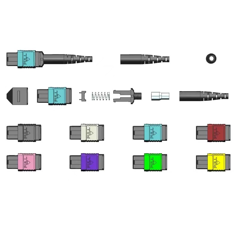
What Must Be Decided for MPO fiber count?
Use the decision table to turn the topic into controlled purchase, design and acceptance inputs. Each row should be confirmed against the actual equipment, route and destination standard rather than copied from a generic catalogue.
| Decision area | What to specify | Why it matters | Evidence to retain |
|---|---|---|---|
| Active interface | Lane count and optical direction from equipment | Determines live fibres | Transceiver and switch documentation |
| MPO geometry | One-row or two-row interface and width | Controls physical compatibility | IEC 61754 part and drawing |
| Trunk utilization | Live, spare and unused positions | Affects cost and migration | Fibre map by link type |
| Breakout method | Cassette, harness or direct parallel link | Changes connector count and polarity | End-to-end channel diagram |
| Future state | Approved migration rather than vague headroom | Avoids stranded fibres | Signed migration matrix |
How to Control MPO fiber count in the Project
The controls below connect the drawing, sample, production lot and installed result. They are deliberately practical: each one produces a record that procurement, engineering and field teams can review later.
Start at the transceiver
Read the equipment interface and lane assignment. Do not infer fibre count from Ethernet speed alone because different optical variants can use different architectures.
Identify rows and pin status
State male or female, key orientation and the applicable one-row or two-row geometry. A mating connector must not be specified by fibre count alone.
Calculate utilization by channel
Map every position through trunk, cassette or harness. Mark unused fibres explicitly so they are not mistaken for spare live paths during commissioning.
Keep migration reversible
Choose modules and trunks that support the documented next interface without creating untestable polarity combinations. Record which components change at each stage.

Acceptance and Handover Checks
Agree the method and disposition before testing begins. A result without a defined record owner or failure action is difficult to use during shipment release or commissioning.
| Check | Method | Record | Failure action |
|---|---|---|---|
| Interface match | Compare connector drawing to equipment | Approved interface sheet | Stop incompatible order |
| Continuity map | Test every fibre position | Serialized map | Correct or reject crossed fibres |
| Pin and key | Inspect both ends | End-face photographs | Replace wrong gender or orientation |
| Optical result | Test live and required spare fibres | Per-fibre data | Quarantine failing assembly |
| Migration trial | Build one complete target channel | Pilot report | Revise architecture before volume |
Standards and Evidence to Put Behind the Purchase Order
This IEC publication defines two-row MPO interface dimensions. See IEC 61754-7-2 two-row MPO interface.
This IEC publication covers the two-row, 16-fibre-wide MPO interface. See IEC 61754-7-3 16-fibre-wide MPO interface.
This IEC procedure addresses attenuation, polarity and length testing for installed MPO-terminated cabling. See IEC 61280-4-5 MPO cabling test procedure.
Decision tree
The right MPO count is the smallest documented interface that serves the required lane map and migration path without avoidable stranded positions. Approve it with an end-to-end fibre map.
- Confirm equipment lane map
- Specify MPO rows, pins and key
- Map all fibre positions
- Test each required fibre
- Pilot the planned migration channel
For a project-specific quotation, review Fenxi’s MPO connector range, MPO/MTP patch cords, MPO trunk cable specification guide, and MPO polarity methods guide. Send the destination market, connector interfaces, fibre type, cable construction, quantities, drawing revision and required test records. The response can then separate standard catalogue options from items that need confirmation or custom tooling.