
An MPO breakout harness drawing must map every MPO position to a named breakout connector and polarity position. A generic Method A, B or C label is insufficient when the harness converts parallel lanes to duplex channels or uses custom equipment numbering.
Harnesses compress many paths into one assembly, so a single drawing error can reverse multiple services. The safest document combines an MPO face view, breakout-end labels, cable-leg lengths, pin and key details, and a continuity table. The test report should use the same identifiers.
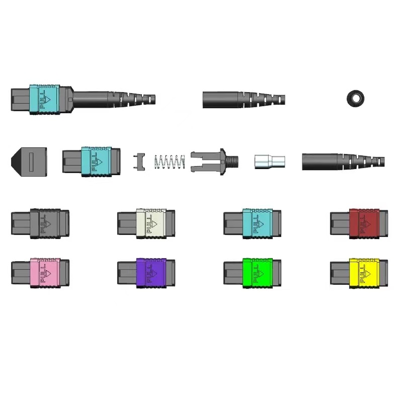
What Must Be Decided for MPO harness polarity?
Use the decision table to turn the topic into controlled purchase, design and acceptance inputs. Each row should be confirmed against the actual equipment, route and destination standard rather than copied from a generic catalogue.
| Decision area | What to specify | Why it matters | Evidence to retain |
|---|---|---|---|
| Viewing direction | Looking into plug or from cable side | Prevents mirrored numbering | Drawing note |
| MPO face | Pins, key, rows and position numbers | Defines the trunk endpoint | Face diagram |
| Breakout legs | Connector ID, polarity and length | Controls equipment mapping | Leg schedule |
| Labels | Permanent ID at trunk and each leg | Supports installation and replacement | Label artwork |
| Continuity | Measured position-to-leg map | Proves the build | Serialized test report |
How to Control MPO harness polarity in the Project
The controls below connect the drawing, sample, production lot and installed result. They are deliberately practical: each one produces a record that procurement, engineering and field teams can review later.
Use one numbering system
Carry the same fibre and leg identifiers through drawing, labels, test file and port schedule. Translation tables create avoidable commissioning errors.
Show duplex orientation
For LC duplex breakouts, identify A and B positions or transmit and receive roles. A leg number alone does not prove the clip orientation.
Control stagger lengths
Dimension each leg from a common reference and state tolerance. Staggering should match equipment port layout without placing load on short branches.
Freeze custom maps
Custom polarity requires a unique part number and drawing revision. Do not allow it to share packaging with a standard harness that looks identical.

Acceptance and Handover Checks
Agree the method and disposition before testing begins. A result without a defined record owner or failure action is difficult to use during shipment release or commissioning.
| Check | Method | Record | Failure action |
|---|---|---|---|
| Face diagram | Compare plug to drawing | Inspection photo | Correct wrong key or pins |
| Leg labels | Read every identifier | Label audit | Relabel before test |
| Continuity | Test every position | Position map | Rework crossed fibres |
| Length | Measure overall and leg lengths | Dimensional report | Hold out-of-tolerance unit |
| Equipment trial | Install pilot harness | Port-level sign-off | Revise map or stagger |
Standards and Evidence to Put Behind the Purchase Order
This IEC publication defines two-row MPO interface dimensions. See IEC 61754-7-2 two-row MPO interface.
This IEC procedure addresses attenuation, polarity and length testing for installed MPO-terminated cabling. See IEC 61280-4-5 MPO cabling test procedure.
The 2024 edition specifies inspection and testing of installed optical-fibre cabling. See ISO/IEC 14763-3:2024 optical cabling testing.
Commissioning checklist
The continuity table is the controlling truth for a harness. Make the drawing, labels and test export use the same position names so field teams can verify the path without interpretation.
- State viewing direction
- Draw pins, key and positions
- Label every breakout leg
- Measure the complete map
- Assign a unique part number to custom polarity
For a project-specific quotation, review Fenxi’s MPO connector range, MPO/MTP patch cords, MPO trunk cable specification guide, and MPO polarity methods guide. Send the destination market, connector interfaces, fibre type, cable construction, quantities, drawing revision and required test records. The response can then separate standard catalogue options from items that need confirmation or custom tooling.