
A low-loss MPO link should be accepted against a route-specific budget and a defined measurement method, not a vendor adjective. Test every required fibre position, verify polarity and inspection condition, and keep measurement uncertainty visible when results sit near the limit.
Parallel links can fail when one lane is weak even if the average loss looks good. Connector count, cassette internals, reference interfaces and cleaning condition all affect the result. IEC 61280-4-5 provides a method for MPO-terminated installed cabling, but the project still has to define the topology and acceptance limit.
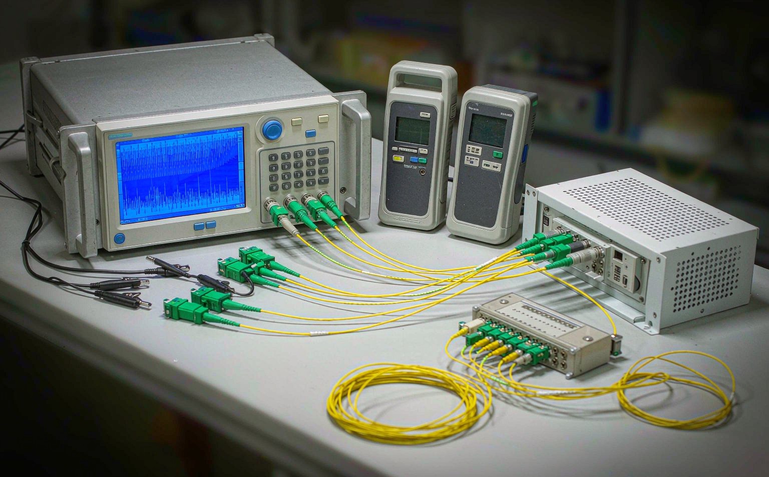
What Must Be Decided for MPO low loss acceptance test?
Use the decision table to turn the topic into controlled purchase, design and acceptance inputs. Each row should be confirmed against the actual equipment, route and destination standard rather than copied from a generic catalogue.
| Decision area | What to specify | Why it matters | Evidence to retain |
|---|---|---|---|
| Budget | Allocated loss for each connection and segment | Creates objective limit | Approved link calculation |
| Reference method | Test interfaces and zero-reference procedure | Controls comparability | Instrument setup record |
| Per-fibre data | Result for every required position | Finds weak individual lanes | Serialized result file |
| Polarity | Position map through full channel | Separates mapping from loss | Continuity report |
| Uncertainty | Instrument, reference and repeatability contribution | Matters near pass limit | Uncertainty statement |
How to Control MPO low loss acceptance test in the Project
The controls below connect the drawing, sample, production lot and installed result. They are deliberately practical: each one produces a record that procurement, engineering and field teams can review later.
Build the budget before testing
List every mated pair, splice, module and fibre segment in the installed route. A test limit created after results arrive encourages selective interpretation.
Inspect before connection
Save images of all accessible MPO faces before loss testing. This prevents contamination from being treated as a stable component characteristic.
Report lanes individually
Do not release a parallel link on average loss. Keep the worst lane, spread and position identity so the result matches the active interface.
Retest under a controlled rule
Define when cleaning, reference reset or repeat measurement is allowed. Preserve both original and repeat results with the reason for the second test.

Acceptance and Handover Checks
Agree the method and disposition before testing begins. A result without a defined record owner or failure action is difficult to use during shipment release or commissioning.
| Check | Method | Record | Failure action |
|---|---|---|---|
| Inspection | Capture all mating faces | Image set | Clean or replace |
| Reference | Set and verify reference | Setup file | Reset invalid reference |
| Loss | Measure every required fibre | Per-position table | Quarantine failing lane |
| Polarity | Verify position map | Continuity record | Correct mapping |
| Closeout | Review margin and uncertainty | Signed report | Engineering review near limit |
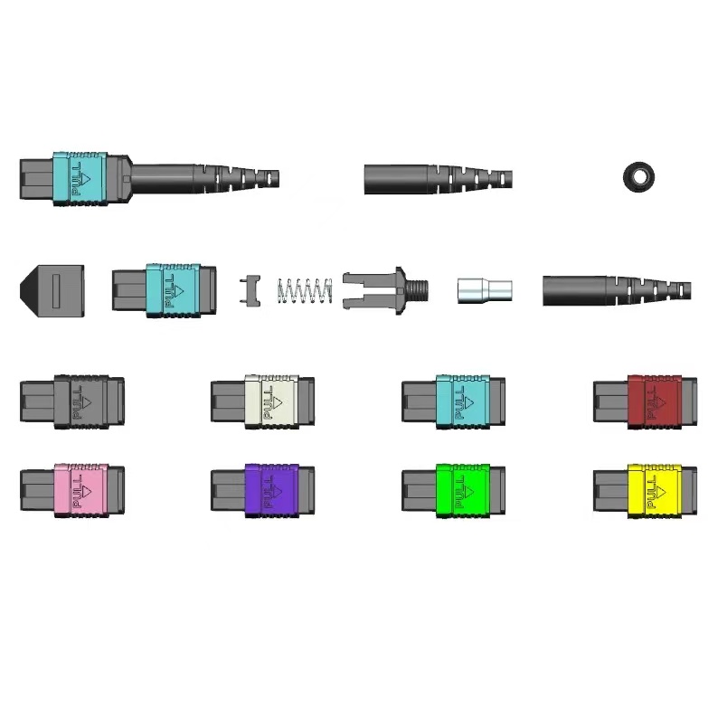
Standards and Evidence to Put Behind the Purchase Order
This IEC procedure addresses attenuation, polarity and length testing for installed MPO-terminated cabling. See IEC 61280-4-5 MPO cabling test procedure.
The 2022 edition covers end-face debris, scratches and defects and states that visual inspection does not replace optical qualification. See IEC 61300-3-35 connector inspection.
The 2024 edition specifies inspection and testing of installed optical-fibre cabling. See ISO/IEC 14763-3:2024 optical cabling testing.
Lab conclusion
Low loss becomes an auditable requirement only when topology, method, position-level data and uncertainty are recorded together. Keep the inspection images with the same channel report.
- Approve the budget first
- Inspect every face
- Use a defined reference method
- Report each fibre position
- Control retest decisions
For a project-specific quotation, review Fenxi’s MPO connector range, MPO/MTP patch cords, MPO trunk cable specification guide, and MPO polarity methods guide. Send the destination market, connector interfaces, fibre type, cable construction, quantities, drawing revision and required test records. The response can then separate standard catalogue options from items that need confirmation or custom tooling.