
Two suppliers quote the same 0.20 dB insertion loss and the same ≥55 dB return loss on a single-mode patch cord, yet one lot intermats cleanly across a whole rack while the other triggers reflectance faults at the first field test. The fiber, the cable and the polish label are usually identical. The difference sits in the three-dimensional shape of the ferrule end face, measured in micrometres and nanometres — and it is the one line most purchase orders never state.

What End-Face Geometry Actually Measures
Two connectors mate because the spring in each housing drives the polished ferrule tips together hard enough to deform the glass slightly. Whether that deformation produces true physical contact depends on four numbers, and every one of them is an output of the polishing process rather than the parts list.
Radius of curvature is the radius of the spherical dome polished onto the tip. A dome that is too flat behaves like a plane and leaves an air gap at the centre of the joint; a dome that is too sharp concentrates the mating force on a small area and loses contact as soon as the spring load relaxes. PC and UPC tips are polished between roughly 7 and 25 mm, while APC tips, cut at 8°, sit between 5 and 12 mm.
Apex offset is the distance between the highest point of that dome and the axis of the fiber. When two tips with large offsets meet, contact happens at their high points instead of on the fiber cores, which opens a small air gap and pushes reflectance up. Anything beyond 50 µm is out of specification for single-mode work, and the number is the same for UPC and APC.
Fiber height describes whether the fiber protrudes from or sits below the ceramic surface — the protrusion and undercut values on a polishing report. A few tens of nanometres of protrusion guarantees that glass, not ceramic, carries the contact. Push it too far and the fiber takes the full spring load and can crack; leave it recessed and the joint never closes.
Polish angle and keying apply only to APC. The 8° cut turns reflection away from the source, and it works only if both halves carry the same angle, because the return loss of an angled joint collapses long before its insertion loss does. The angle is also measured relative to the connector key, so a keyway error presents a perfectly polished tip as a badly angled one. That is the mechanical reason behind the rule that APC and UPC assemblies stay in separate link segments.
Concentricity is the fifth parameter worth knowing: how precisely the fiber core sits on the ferrule axis. It belongs to the ferrule rather than the polish, and single-mode assemblies are normally held inside about 1 µm. A lateral core offset adds insertion loss that no amount of cleaning removes, and the connector identification reference published by the Fiber Optic Association is a useful cross-check when two vendors describe the same interface differently.
The Limits Behind the Numbers
For single-mode assemblies the reference documents are Telcordia GR-326-CORE Issue 4 and the IEC 61755 series, which fixes both the measurement method and the acceptance bands for PC, UPC and APC interfaces. These are the figures that recur in qualified specifications.
| Parameter | UPC / PC single-mode | APC single-mode | What fails outside the band |
|---|---|---|---|
| Radius of curvature | 7–25 mm | 5–12 mm | Flat tips never close at the core; sharp tips load a small area |
| Apex offset | ≤50 µm | ≤50 µm | Contact lands off the fiber axis and leaves an air gap |
| Fiber height | −125 to +50 nm across the 7–25 mm range | Same band; ±100 nm is commonly quoted | High protrusion cracks the fiber; deep undercut keeps the joint open |
| Polish angle | Not applicable | 8.0° ± 0.3° | Angle mismatch opens a wedge gap and destroys return loss |
| Core concentricity | Typically ≤1 µm | Typically ≤1 µm | Lateral core offset adds loss that cleaning cannot recover |
| Key alignment | Not applicable | Cut plane referenced to the keyway | A good tip measures as a bad angle when the key is rotated |
Note how wide the radius band is and how narrow the fiber height band is. Buyers who accept a delivery on a sample of moulded shells rather than on a geometry report are effectively buying whatever the polisher’s pad pressure produced that day. TIA intermateability standards exist for exactly this reason: they define the interface, not the process that produced it.
How a Geometry Defect Shows Up in the Field
Geometry problems rarely appear at the factory gate. They surface as a test result that will not repeat, or as a link that degrades after its first re-mate.
| Field symptom | Likely geometry cause | First check |
|---|---|---|
| Insertion loss is fine but return loss sits near the limit | Radius of curvature at the flat end of the band, so physical contact is weak | Interferometer reading on both halves of the pair |
| Link passes on the bench, fails against another vendor’s cord | Apex offset or a large radius difference between the two domes | Measure both ends, then re-test mated as a pair |
| Fibers crack, or loss jumps after repeated mating | Protrusion far above +50 nm, so the spring load sits on the glass | Fiber height column of the geometry report |
| APC pair shows reflectance far above expectation | Polish angle outside 8.0° ± 0.3°, or a key error | Angle value plus key orientation |
| MPO trunk shows a wide spread of per-fiber losses | Uneven fiber height across the ferrule row | Per-fiber height and coplanarity data |
| A clean duplex cord still tests high | Core off the ferrule axis, or a worn alignment sleeve | Check the adapter as well as the cord |
The last row is worth a note: an alignment sleeve that has lost its bore tolerance adds lateral offset to every cord plugged into it, and the cord gets blamed because it is the part that was tested last. Keep a spare known-good cord as a reference and swap it in before condemning a shipment.
Multi-Fiber Ferrules Are Judged Differently

An MT ferrule carries 12, 16 or 24 fibers inside one moulded tip aligned by two guide pins, and it is judged by coplanarity rather than by a symmetric fiber height value. Every fiber in the row has to sit inside one band so that all of them reach contact within the same spring travel, and IEC 61755-3-31 defines the geometry requirement for the minus side of the ferrule. One low fiber in a twelve-fiber row produces a link where eleven channels test green and one reads high loss, which is why a per-ferrule geometry sheet matters as much as the channel loss test.
The same 8° angle applies to angled MPO/MTP cable assemblies, but with a twist: the guide pins set the reference plane for the whole row, so a bent pin or a worn adapter shifts the angle across all fibers at once. US Conec developed the MTP brand and publishes guidance on ferrule handling that is worth reading before a high-density rack build, and the same care applies to any 12-fiber trunk in a data center.
Why an Insertion Loss Meter Cannot See Any of This
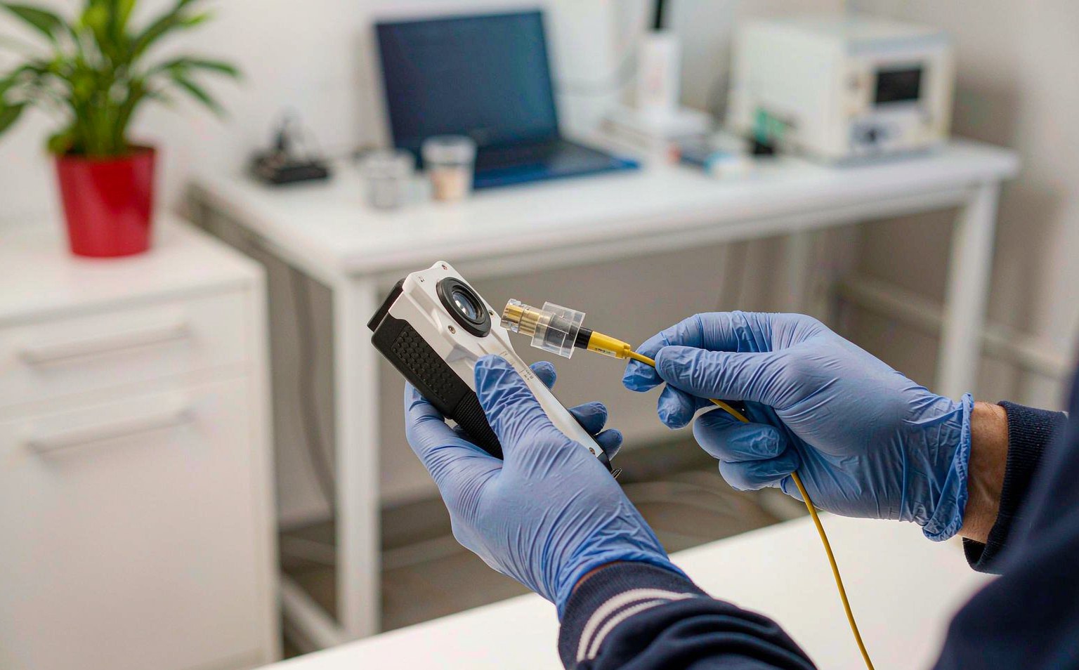
A light source and power meter measure the result of a joint, not the geometry that produced it. A 3D interferometer measures the tip itself, mapping the dome and reporting radius of curvature, apex offset, fiber height and, for APC, the angle relative to the key in seconds per connector, following the methods set out in the IEC 61755 series.
That distinction matters at procurement, not only at the test bench. An insertion loss figure says nothing about whether the two tips will still make physical contact after a re-mate, a thermal cycle or a slightly softer spring. Geometry data does, and it is the data that predicts how a connector behaves once the dust cap comes off. A pass mark on an insertion loss report is not a substitute for it.
A practical sampling policy keeps the cost sane: 100 per cent interferometer screening on APC single-mode where return loss carries the link, and lot-based sampling on UPC premise cords, with the report shipped alongside the certificates. The inspection guidance from Fluke Networks covers the visual half of the same discipline, and the two checks belong in the same work instruction.
Geometry Specification Checklist for the RFQ
Geometry is the cheapest quality dimension to control, because it costs one line in the enquiry and one report in the shipping documents. Hand the table below to your supplier and ask for the data before the first lot ships.
| Parameter | What to write in the RFQ | Evidence to request |
|---|---|---|
| Radius of curvature | 7–25 mm for UPC; 5–12 mm for APC | Interferometer report per production lot |
| Apex offset | ≤50 µm on every assembly | Same report, per connector |
| Fiber height | −125 to +50 nm, and state whether ±50 nm or ±100 nm is required | Same report |
| Polish angle | 8.0° ± 0.3° measured against the key | Same report, angle in degrees |
| Concentricity | Core-to-ferrule offset ≤1 µm for single-mode | Ferrule certificate from the tip supplier |
| MT coplanarity | Minus-side coplanarity per IEC 61755-3-31 plus a per-fiber height spread limit | Per-ferrule geometry sheet |
| End-face quality | No defect in the 50 µm core zone, per IEC 61300-3-35 | 400× inspection image |
| Mating durability | Insertion and return loss measured after the mating sequence of GR-326-CORE | Qualification test summary |
Read the reports the way you would read a loss budget: the parameter that sits at the edge of its band on the incoming inspection is the one that will drift out of it in the field. Fenxi records insertion loss, return loss and end-face geometry for every assembly it ships, from SC connectors and single-mode and multimode patch cords to angled MPO trunks. Send your link design, the polish type per segment and the limits you intend to enforce, and our engineers will confirm the geometry specification and quote the assemblies against your rollout.