Introduction: The Critical Role of Fiber Optic Connections in a Data-Driven World
Imagine this: a major financial trading firm loses 30 milliseconds of connectivity during peak market hours because a single contaminated fiber connector caused a 3 dB insertion loss spike. That 30-millisecond interruption cost them an estimated $4.7 million in missed arbitrage opportunities. This is not fiction—it happens more often than the industry cares to admit.
Fiber optic networks are no longer exotic infrastructure reserved for telecom carriers and hyperscale data centers. They are the backbone of everything from hospital diagnostic imaging systems to smart factory automation, from 5G fronthaul networks to the fiber-to-the-home connection delivering Netflix to your living room. At the center of every one of these networks, making the physical connections that enable light to travel from source to destination, sits a device few end users ever see: the fiber optic connector.
Among the many connector types available today—LC, ST, FC, MPO, and others—the SC connector remains one of the most widely deployed and trusted interfaces in the industry. Specifically, the SC to SC bulkhead connection is the workhorse of fiber extension in patch panels, wall outlets, distribution frames, and equipment interfaces worldwide. Get the specification, installation, and maintenance of these connections right, and your network delivers decades of near-lossless performance. Get it wrong, and you inherit a lifetime of intermittent faults, escalating bit error rates, and unexplained downtime.
The fiber optic connectors market has been expanding at a notable pace. Valued at approximately 5.61billionin2025,itisprojectedtogrowto5.98 billion in 2026 at a compound annual growth rate of 6.5%. This growth is driven by surging demand for high-bandwidth connectivity, 5G deployment, and data center expansion. With each new connection point, the importance of proper connector selection and termination grows proportionally.
This guide is written for network engineers, fiber optic technicians, data center managers, and anyone responsible for building or maintaining fiber optic links. We will explore every facet of using SC to SC connectors for reliable fiber optic extension: understanding the connector design, selecting the right polish type (UPC vs. APC), calculating loss budgets, executing proper cleaning and inspection protocols, and troubleshooting common failures. By the end, you will have a comprehensive framework for specifying, installing, and maintaining SC to SC connections that perform reliably for decades.
Chapter 1: Understanding the SC Connector — Design, Standards, and Evolution
Before we dive into the practical details of extending fiber using SC to SC connections, we need to understand exactly what an SC connector is, how it evolved, and why it has remained relevant for over three decades.
1.1 What Is an SC Connector?
SC stands for Subscriber Connector—sometimes also referred to as Standard Connector or Square Connector. Developed by Nippon Telegraph and Telephone (NTT) in the mid-1980s, the SC connector was designed to address the limitations of earlier connector types like the ST (Straight Tip), which used a bayonet-style twist-lock mechanism that was prone to misalignment during mating.
The SC connector uses a push-pull coupling mechanism: you push the connector into the adapter to engage it, and you pull the connector body to release it. This simple, intuitive action eliminates the rotational movement that can cause ferrule end-face scratching and variable insertion loss in twist-lock designs. The push-pull design also enables higher-density installations, as connectors can be placed closer together without requiring finger clearance for twisting.
The SC connector body is rectangular in cross-section, typically molded from engineered thermoplastic, and features a 2.5 mm diameter ferrule—the precision ceramic cylinder that holds the optical fiber precisely centered. This 2.5 mm ferrule is the same diameter used in FC and ST connectors, which means SC connectors share the same basic alignment physics that have been refined over decades.
1.2 Standards Governing SC Connectors
The SC connector is defined by a comprehensive set of international standards that ensure interoperability between manufacturers and predictable performance in the field. The primary standards are:
IEC 61754-4 specifies the standard interface dimensions for the type SC family of connectors. The most recent edition (2021, published as the third edition) cancels and replaces the 2013 second edition and constitutes a technical revision. This standard ensures that any compliant SC connector will mechanically mate with any compliant SC adapter, regardless of manufacturer.
TIA-604-3 is the American National Standards Institute (ANSI) counterpart standard, defining the same interface in the TIA framework. Along with IEC 61755-3-1, which covers end-face geometry, these standards form the foundation of SC connector interoperability.
IEC 60874-19-3 provides a detail specification specifically for the SC duplex adapter used with multimode fiber connectors, defining parameters such as insertion force (typically ≤30 N), durability (≥500 mating cycles), and material requirements for the adapter housing.
The SC connector’s development paralleled the introduction of Physical Contact (PC) ferrules, which provide low-loss connections without requiring index-matching gel between the mated end-faces. This was a significant advancement over earlier flat-polish connectors that required gel to fill the air gap between fiber ends—a maintenance headache that degraded over time.
1.3 Why SC Remains Relevant in the Age of Small Form Factors
The fiber industry has introduced numerous small form factor connectors over the years—LC, MU, CS, SN—all designed to pack more connections into less space. The LC connector, with its 1.25 mm ferrule (half the diameter of the SC’s 2.5 mm ferrule), has become the dominant connector in high-density data center applications.
Yet SC persists, and for good reason. The larger 2.5 mm ferrule is more robust against contamination and physical damage than smaller ferrules. SC connectors are easier to handle in the field, particularly for technicians wearing gloves in outdoor or industrial environments. They tolerate higher mating cycle counts without degradation. And in many applications—FTTH (Fiber to the Home), CATV, enterprise backbone cabling—connection density is not the primary constraint; reliability and ease of maintenance are.
In fact, some newer connector designs like the CS and SN are actually pushing density beyond LC, but SC remains the go-to choice for applications where the connection will be accessed frequently, exposed to environmental stress, or required to maintain performance over 20-plus years of service life.
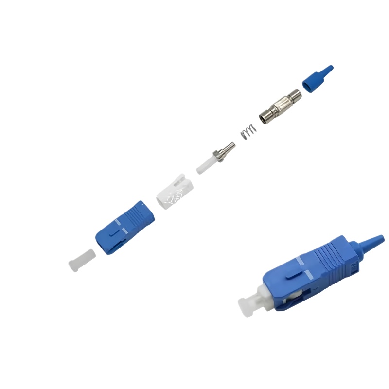
Chapter 2: The Anatomy of an SC to SC Fiber Extension
When we talk about using an SC to SC connector for fiber optic extension, we are really talking about three components working together as a system: the connector on the source cable, the adapter or coupler that joins them, and the connector on the extension cable. Understanding each component’s role and how they interact is essential for specifying a reliable extension.
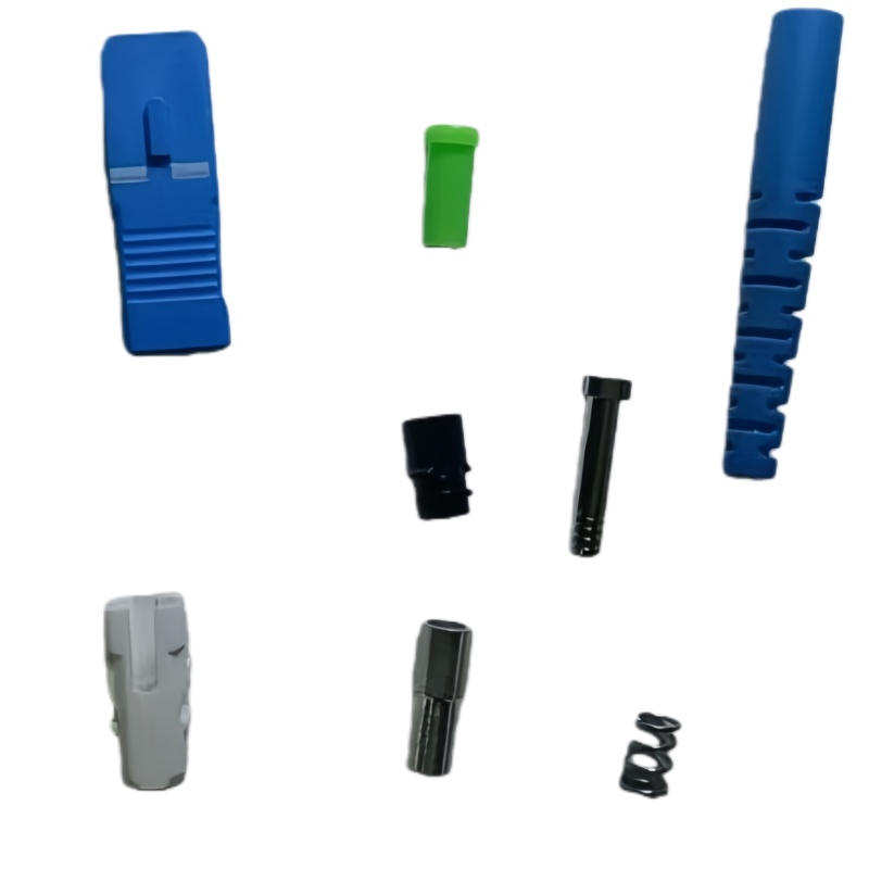
2.1 The SC Connector: Key Components
An SC connector consists of several precision components:
The Ferrule: This is the heart of the connector—a cylindrical component, typically made of zirconia ceramic, with a microscopic hole precisely centered along its axis. The optical fiber is inserted through this hole and bonded in place with epoxy. The ferrule end-face is then cleaved and polished to a precise geometry. For single-mode applications, the ferrule hole diameter is approximately 126 µm (to accommodate a 125 µm cladding diameter fiber). For multimode, it is approximately 127 to 128 µm.
The Connector Body: A molded plastic housing that holds the ferrule in precise alignment, provides the push-pull latching mechanism, and incorporates a spring that applies controlled axial force (typically 8 to 12 Newtons) to maintain physical contact between mated ferrule end-faces.
The Boot: A flexible strain relief that protects the fiber where it exits the connector body, preventing sharp bends that could cause microbending loss or fiber breakage.
The Dust Cap: A small but critical component. Every unmated SC connector should have a dust cap installed. Contamination is the leading cause of fiber connector failure, and a dust cap is the first line of defense.
2.2 The SC Adapter (Bulkhead Coupler)
The SC adapter—also called a coupler or bulkhead—is the component that mates two SC connectors together. It is the bridge in your extension. SC adapters are available in several configurations:
Simplex vs. Duplex: A simplex adapter mates a single fiber pair. A duplex adapter mates two fibers simultaneously (transmit and receive), with the two connector positions mechanically linked. Duplex SC adapters are the standard for most networking applications where bidirectional communication is required.
Bulkhead Mount vs. In-Line: Bulkhead adapters are designed to mount through a panel, wall plate, or enclosure wall, providing a fixed connection point. In-line adapters connect two cables directly without mounting. For fiber extensions, bulkhead configurations are most common because they provide a structured, protected transition point.
Flanged vs. Flangeless: Flanged adapters include mounting ears for screw or snap-in panel mounting. Flangeless adapters are designed for high-density applications where they are held in place by the panel cutout geometry.
Alignment Sleeve Material: This is where single-mode and multimode adapters fundamentally differ. Single-mode SC adapters use a zirconia ceramic split sleeve for alignment. Zirconia offers superior hardness, wear resistance, and thermal stability, maintaining precise alignment over thousands of mating cycles. Multimode adapters traditionally used phosphor bronze sleeves, though zirconia is increasingly used in multimode applications as well for its superior performance.
The SC adapter provides a quick and easy solution to extend an existing piece of fiber optic cabling, built with high-grade casing materials designed for longevity. It is ideal as a bulkhead or coupler in optical distribution networks, maintaining low signal loss and high stability on critical links.
2.3 The Extension Cable Assembly
The final component is the SC-terminated extension cable itself. This cable must match the fiber type (single-mode or multimode), core diameter, and polish style of the source connection. The quality of this cable—the fiber itself, the connector termination quality, the polish finish—directly determines the performance of the entire extension.
Chapter 3: Single-Mode vs. Multimode SC Extensions — Making the Right Choice
One of the most fundamental decisions when specifying an SC to SC fiber extension is the fiber type. Choosing wrong can render your extension unusable, introduce excessive loss, or limit future bandwidth upgrades.
3.1 Core Diameter and Light Propagation
The difference between single-mode and multimode fiber lies in the core diameter and how light propagates through the fiber.
Single-mode fiber uses a core diameter of 9 microns (with a 125-micron cladding), typically expressed as 9/125 µm. This narrow core allows only one mode (path) of light to propagate, eliminating modal dispersion—the spreading of light pulses that limits bandwidth over distance. Single-mode fiber is used for long-distance data transmission, typically spanning kilometers to hundreds of kilometers.
Multimode fiber uses a larger core—either 62.5 microns (OM1) or 50 microns (OM2, OM3, OM4, OM5)—with the same 125-micron cladding. The larger core allows multiple light modes to propagate simultaneously, which introduces modal dispersion and limits practical transmission distance. Multimode fiber is normally used for short distance data transmission, typically within buildings or campus environments.
3.2 Ferrule Material Differences
The ferrule construction differs between single-mode and multimode SC connectors:
Single-mode connectors almost always use a zirconia (ceramic) ferrule, which provides the precision bore concentricity and surface finish required for sub-micron core alignment. Zirconia’s hardness ensures that the ferrule end-face maintains its polished geometry through repeated mating cycles.
Multimode connectors can use stainless steel (nickel-silver), composite plastic, or zirconia ferrules. The larger core of multimode fiber is more forgiving of alignment tolerances, allowing lower-cost ferrule materials to be used. However, premium multimode connectors increasingly use zirconia ferrules for improved repeatability.
3.3 Color Coding for Identification
The fiber industry uses a standardized color-coding system for SC connectors and adapters to prevent mismating:
- Single-mode UPC connectors and adapters: Blue housing, blue adapter body
- Single-mode APC connectors and adapters: Green housing, green adapter body
- Multimode UPC connectors and adapters: Beige or black housing, beige adapter body
- OM3/OM4 multimode (aqua fiber): Aqua housing on some premium assemblies
This color coding exists specifically to help distinguish corresponding cables during cabling work, providing a visual check against incorrect mating.
Table 1: SC Connector Selection Guide by Application
| Application | Distance | Fiber Type | Polish | Connector Color | Typical IL per Connection | Typical RL |
|---|---|---|---|---|---|---|
| FTTH Drop Link | 0–20 km | Single-mode | APC (Green) | Green | ≤0.30 dB | ≥60 dB |
| CATV Distribution | 0–30 km | Single-mode | APC (Green) | Green | ≤0.25 dB | ≥65 dB |
| Enterprise LAN Backbone | <550 m | MM OM3/OM4 | UPC (Beige/Aqua) | Beige/Aqua | ≤0.20 dB | ≥30 dB |
| Data Center Interconnect | <100 m | MM OM4/OM5 | UPC (Beige/Aqua) | Beige/Aqua | ≤0.15 dB | ≥30 dB |
| Telecom Core Network | 20–120 km | Single-mode | UPC (Blue) | Blue | ≤0.30 dB | ≥50 dB |
| Harsh Industrial | <2 km | Single-mode | APC (Green) | Green | ≤0.35 dB | ≥60 dB |
| RF over Fiber (5G Fronthaul) | 0–20 km | Single-mode | APC (Green) | Green | ≤0.25 dB | ≥60 dB |
| Laboratory/Test Equipment | <100 m | Single-mode or MM | UPC | Blue/Beige | ≤0.20 dB | ≥50 dB |
*Sources: Compiled from industry specifications (TIA-568, IEC 61755) and manufacturer datasheets*
Chapter 4: UPC vs. APC Polish — The Decision That Defines Return Loss
Within the SC connector family, the most significant performance distinction is the ferrule end-face polish: Ultra Physical Contact (UPC) or Angled Physical Contact (APC). This choice directly determines return loss (reflectance)—and in many networks, return loss is what separates a reliable connection from a problematic one.
4.1 Understanding Return Loss
Return loss measures the amount of light reflected back toward the source from the connector interface. When light traveling through a fiber encounters a change in refractive index—such as the glass-to-air-to-glass transition at a connector junction—a portion of the light is reflected backward. This reflected light can interfere with laser stability, increase bit error rates, and cause distortion in analog systems.
Return loss is expressed as a negative number in decibels (dB); the more negative the number, the better (less reflection). Think of it as an echo: a large echo (poor return loss) disrupts the original signal, while a small echo (good return loss) is imperceptible.
4.2 UPC Performance Characteristics
UPC connectors feature a domed end-face with zero-degree angle—the ferrule end is polished flat but with a slight radius to ensure physical contact between fiber cores when mated. Industry standards specify that UPC connectors achieve return loss of –50 dB or better on good single-mode connections.
The –50 dB figure means only 0.001% of the transmitted light is reflected back—a tiny fraction. For most digital transmission systems, including Gigabit Ethernet and 10 Gigabit Ethernet, this level of reflection is well within acceptable limits. UPC has become the default choice for many Ethernet and telecom links.
However, UPC performance can degrade with temperature cycling, contamination, and mechanical wear. Independent testing per Telcordia GR-326 standards shows that while UPC assemblies start at –50 dB return loss, they can drop to –45 dB after 500 temperature cycles.
4.3 APC Performance Characteristics
APC connectors feature an 8-degree angled end-face. This angle causes any light reflected at the glass-to-air interface to be directed into the cladding rather than back down the fiber core. The result is dramatically lower reflectance.
Industry standards specify APC return loss at –60 dB or better—a full order of magnitude improvement over UPC. At –60 dB, only 0.0001% of transmitted light is reflected. More critically, APC connectors maintain this return loss better across temperature cycles. The same Telcordia GR-326 testing shows APC assemblies retain ≥60 dB return loss after 500 cycles, while UPC can degrade to –45 dB.
Green vs. blue dilemma: APC’s 8-degree angle minimizes return loss to –60 dB, essential for analog TV and RF applications where UPC hits only –50 dB.
4.4 Application-Driven Selection
The choice between UPC and APC is driven by the application’s sensitivity to reflected light:
When to Choose UPC (Blue Connectors):
- Standard Ethernet and IP networks (1G, 10G, 25G, 40G)
- Most enterprise LAN and data center applications
- Applications where cost is a primary concern (UPC connectors are typically 10–20% less expensive)
- Digital systems tolerant of moderate reflectance
When to Choose APC (Green Connectors):
- CATV and analog RF video distribution systems
- RF over fiber applications (including 5G fronthaul)
- FTTx passive optical networks (PON)
- High-power fiber amplifier systems
- Any system where reflected light can cause laser instability
- Outdoor installations subject to wide temperature swings
Critical Warning: Never mate a UPC connector with an APC connector. The 8-degree angle of APC means the fiber cores will not align properly, producing very poor insertion and return loss—and the angled end-face can physically damage the domed UPC ferrule. The color-coding system (blue for UPC, green for APC) exists precisely to prevent this mistake. If you see green going into blue, stop and verify.
Chapter 5: The SC to SC Bulkhead — Your Extension’s Critical Junction
The SC to SC bulkhead adapter—the component that joins your source cable to your extension cable—is far more than a simple plastic coupler. It is a precision alignment mechanism that determines the optical performance of your entire extension.
5.1 How the Bulkhead Adapter Works
When two SC connectors are inserted into opposite sides of a bulkhead adapter, the adapter’s internal alignment sleeve captures both ferrules and aligns them coaxially. The springs in each connector body press the two ferrule end-faces together with controlled force, establishing physical contact between the polished fiber end-faces.
The alignment sleeve—whether ceramic (zirconia) for single-mode or phosphor bronze for multimode—is the critical element. It must hold the two ferrules with sub-micron concentricity while allowing them to slide axially under spring pressure. Any off-axis tilt or lateral offset at this junction translates directly into insertion loss.
5.2 Mechanical Durability Requirements
Bulkhead adapters are rated for a minimum number of mating cycles—typically 500 cycles per IEC standards. This means the adapter can withstand 500 connector insertions and removals without mechanical degradation affecting optical performance.
For applications where connections will be changed frequently—test labs, patch panels in dynamic environments, temporary deployment setups—this durability rating is important. In these cases, consider adapters with zirconia sleeves even for multimode applications, as ceramic offers superior wear resistance.
5.3 Environmental Sealing Options
For outdoor or harsh environment applications, standard bulkhead adapters may not provide adequate protection. IP68-rated SC bulkhead couplers are available, designed to provide reliable mechanical mating of cable assemblies in harsh or outdoor environments while preventing moisture and dust ingress.
These sealed bulkheads incorporate O-ring seals and robust housing materials that maintain optical performance through temperature extremes (–40°C to +75°C), driving rain, dust exposure, and mechanical vibration. The incremental cost (typically $5–15 per unit) is trivial compared to the downtime caused by a moisture-compromised connection.
Chapter 6: Loss Budgets — Understanding and Calculating Acceptable Loss
Every fiber optic link has a loss budget: the maximum allowable optical attenuation from transmitter to receiver while maintaining reliable communication. Each component in the link—connectors, splices, the fiber itself—consumes a portion of this budget. Understanding how SC to SC connections fit into your loss budget is essential for reliable extension.
6.1 Connector Insertion Loss Standards
Insertion loss (IL) measures the reduction in optical power caused by inserting a component into the link. For fiber optic connectors, industry standards define both maximum and typical values.
The TIA standard specifies a maximum insertion loss of 0.75 dB per connector. However, this figure is deliberately conservative and not particularly realistic, as most fiber connectors typically measure in the range of 0.3 to 0.5 dB for standard loss and 0.15 to 0.2 dB for low loss.
The European standard EN 50173-1:2018 similarly specifies 0.75 dB as the maximum allowed insertion loss for each fiber optic connection.
In practice, premium SC connectors from quality manufacturers routinely deliver:
- Single-mode UPC: 0.15–0.30 dB typical insertion loss
- Single-mode APC: 0.20–0.30 dB typical insertion loss
- Multimode UPC: 0.10–0.25 dB typical insertion loss
6.2 The SC to SC Junction in Your Loss Calculation
An SC to SC bulkhead connection introduces two connector matings: the source connector into the adapter, and the extension connector into the adapter. Each mating contributes its own insertion loss. Therefore, the total loss budget impact of your SC to SC extension is roughly double the per-connector loss.
For example, using premium single-mode UPC connectors with 0.20 dB typical loss per mating, your SC to SC bulkhead junction should add approximately 0.40 dB to the link budget. Using standard-grade connectors at 0.35 dB per mating, the junction adds 0.70 dB—approaching the TIA maximum for a single connection point.
This distinction matters: a chain of three SC to SC extensions (common in patching through multiple panels) using standard connectors could consume 2.1 dB of your link budget, while the same chain using low-loss connectors might consume only 0.90 dB—a difference that could determine whether the link meets its design specification.
6.3 Building a Complete Link Loss Budget
A complete link loss budget accounts for every loss element between transmitter and receiver. The ISO/IEC 14763-3 standard specifies the methodology for testing fiber optic links and provides the framework for budget calculation.
Table 2: Sample Link Loss Budget Calculation — Single-Mode 10 km Link with SC Extension
| Loss Element | Quantity | Loss per Unit (dB) | Total Loss (dB) |
|---|---|---|---|
| Source connector (SC/UPC, premium) | 1 | 0.25 | 0.25 |
| SC to SC bulkhead extension junction (2 matings) | 1 pair | 0.25 per mating | 0.50 |
| Intermediate patch panel SC connections | 2 | 0.25 per mating | 0.50 |
| Destination connector (SC/UPC, premium) | 1 | 0.25 | 0.25 |
| Fiber attenuation (G.652.D SMF at 1310 nm) | 10 km | 0.35 dB/km | 3.50 |
| Fusion splice (mid-span) | 2 | 0.05 per splice | 0.10 |
| Total Calculated Link Loss | 5.10 dB | ||
| System Margin (2.0 dB for aging, repairs, temperature) | 2.00 dB | ||
| Total Loss Budget Required | 7.10 dB |
*Note: This example uses typical loss values from premium components. Actual values should be verified against manufacturer specifications for your specific components. The TIA standard specifies 0.75 dB maximum per connector, while typical field connectors measure 0.3–0.5 dB. Single-mode fiber attenuation typically ranges from 0.2–0.4 dB/km.*
When calculating your own loss budget, use the actual specified loss values from your component manufacturers rather than typical values. If manufacturer data is unavailable, use the TIA maximum of 0.75 dB per connector as a conservative estimate—but understand this will result in a pessimistic budget that may unnecessarily constrain your design.
6.4 OTDR Testing for Verification
After installing an SC to SC extension, verification with an Optical Time Domain Reflectometer (OTDR) is the only way to confirm that each connection point is performing within specification. The OTDR sends light pulses into the fiber and measures the backscattered and reflected light as a function of time, producing a “signature” of the entire link.
For an SC to SC bulkhead connection, the OTDR trace should show:
- A distinct reflective peak at the connector location (higher for UPC, lower for APC)
- The insertion loss of the connection (the drop in the trace level after the connector)
- No “gainers” (apparent negative loss, which indicates mismatched backscatter coefficients between connected fibers)
Each connection should be documented with its measured insertion loss, and any connection exceeding 0.75 dB should be investigated, cleaned, and retested. Connections consistently exceeding this threshold may need to be re-terminated.
Chapter 7: Installation Best Practices for SC to SC Fiber Extensions
A properly specified SC to SC extension can be undermined by poor installation practices. The following best practices are drawn from decades of field experience across telecommunications, data center, and enterprise cabling environments.
7.1 Cable Handling and Bend Radius Management
Optical fiber is glass, and glass breaks when bent too sharply. Every fiber cable has a specified minimum bend radius, typically 10 times the cable outer diameter for installed cable and 20 times for cable under tensile load during pulling.
When routing cables for an SC extension:
- Never pull fiber cable by the connector or boot—always pull by the cable’s strength members
- Do not violate cable bend-radius specifications at any point in the installation
- Use cable management panels, horizontal cable managers, and bend radius guides at all transition points
- Leave service loops (typically 1–3 meters) at both ends of the extension for future re-termination or relocation
7.2 Connector Mating Technique
The push-pull design of SC connectors seems foolproof, but incorrect mating technique can damage connectors and degrade performance:
- Always remove dust caps immediately before mating. Do not remove caps and leave connectors exposed.
- Align the connector key (the raised ridge on the connector body) with the slot in the adapter
- Push the connector straight into the adapter until you feel and hear the latch click
- Do not twist, rock, or apply excessive force. If the connector does not seat smoothly, remove it, inspect, and retry
- After mating, gently tug the connector body (not the cable) to confirm it is latched
- Unused adapter ports should always have dust caps installed
7.3 Cleaning During Installation
This point is so important that we will devote an entire chapter to it. But during installation specifically: inspect, clean, and inspect again every connector end-face before mating, using the procedures described in Chapter 8.
7.4 Documentation and Labeling
Every SC to SC extension should be documented:
- Label both ends of every cable with unique identifiers
- Document the fiber type, connector type, and polish for each connection
- Record OTDR trace data as a baseline for future troubleshooting
- Update your cable management database or labeling scheme immediately
7.5 Temperature Considerations
SC connectors are rated for operation from –40°C to +75°C, but install them within their specified range. Avoid installing connections in locations where they will be exposed to direct sunlight, heat sources, or freezing conditions without appropriate environmental protection. Wide temperature swings can cause differential thermal expansion between the ferrule, alignment sleeve, and connector housing, temporarily affecting insertion loss.
Chapter 8: Cleaning and Inspection — The Most Overlooked Step in Fiber Reliability
If there is one practice that separates reliable fiber networks from problematic ones, it is connector cleaning and inspection. Industry data consistently shows that contamination is the number one cause of fiber connector failure and degraded network performance. The solution is simple in concept but demands discipline in execution.
8.1 Why Cleaning Matters
A single dust particle on a connector end-face—invisible to the naked eye at 1 to 10 microns in diameter—can block a significant portion of the fiber core. On a 9-micron single-mode core, a 5-micron particle can obstruct more than 30% of the light path. The result can be insertion loss spikes of 1 to 3 dB or more, far exceeding the 0.75 dB maximum specified by standards.
Beyond simple blockage, contamination causes physical damage. When two connectors are mated, any debris trapped between the end-faces can scratch the polished surfaces. Over multiple mating cycles, this damage accumulates, permanently increasing insertion loss and degrading return loss.
8.2 The IEC 61300-3-35 Inspection Standard
The international standard governing fiber optic connector end-face inspection is IEC 61300-3-35. This standard defines criteria for inspecting fiber optic end faces and sets allowable limits for particle contamination in critical zones.
The standard divides the connector end-face into concentric inspection zones:
- Zone A: The fiber core itself. For single-mode fiber, the standard prohibits any scratches or defects in this zone—zero tolerance.
- Zone B: The cladding region surrounding the core. Tight limits on scratches and defects.
- Zone C: The adhesive layer area. Moderate limits.
- Zone D: The ferrule outer area (contact zone). The standard now recommends initially inspecting the entire Zone D and attempting to remove loose particles that can migrate to more critical Zones A and B.
For multimode fiber with its larger core, the standard allows scratches of up to 3 microns and up to 4 defects not exceeding 5 microns each.
8.3 Cleaning Methods and Tools
Several cleaning methods are available, each appropriate for different scenarios:
Dry Cleaning (One-Click Cleaners): These handheld tools use a mechanical shuttle mechanism to advance a fresh section of cleaning tape across the connector end-face. They are fast, portable, and effective for light contamination. Use them for field cleaning of connectors before mating.
Wet Cleaning (Lint-Free Wipes + Solvent): For heavy contamination or stubborn residues, use lint-free optical-grade wipes with 99.9% pure isopropyl alcohol or a specialized fiber optic cleaning fluid. Wipe in one direction only (do not scrub back and forth), and allow the solvent to evaporate completely before mating.
Stick Cleaners for Bulkhead Adapters: These tools have a cleaning tip on a thin wand that can be inserted into a bulkhead adapter to clean the internal connector face without removing it from the panel. Essential for cleaning connectors in populated patch panels where rear access is limited.
Compressed Air / Canned Air: Use filtered, oil-free compressed air or specialized optical-grade canned air to blow loose particles off the end-face. Never use industrial compressed air, which contains oil aerosols that contaminate the end-face.
8.4 The Inspect-Clean-Inspect Protocol
The fundamental discipline is: always inspect before cleaning, clean, then inspect again. Never mate a connector without final inspection.
- Inspect: Use a fiber inspection microscope (200x or 400x magnification) to examine the connector end-face
- Assess: Compare the image against IEC 61300-3-35 criteria. Determine if cleaning is required
- Clean: Apply appropriate cleaning method based on contamination type
- Re-Inspect: Verify cleanliness. If contamination persists, repeat cleaning or escalate
- Mate: Only mate the connector once the end-face passes inspection
- Document: For critical links, save inspection images as part of the installation record
8.5 Common Cleaning Mistakes to Avoid
- Never touch a connector end-face with your finger. Skin oils are difficult to remove and attract dust.
- Never use cotton swabs or paper-based products on connector end-faces. They leave lint behind.
- Never blow on a connector with your mouth. Breath contains moisture and particulates.
- Never reuse cleaning wipes or one-click cleaner tips. They transfer contamination from one connector to another.
- Never use alcohol that is not certified as reagent-grade or optical-grade. Standard rubbing alcohol contains additives and water that leave residue.
- Never mate connectors without dust caps when not in use. Even minutes of exposure in a typical equipment room deposits particles.
Chapter 9: Troubleshooting Common SC to SC Extension Problems
Even with proper specification and installation, problems can arise. Here is a systematic approach to diagnosing and resolving the most common SC to SC extension failures.
9.1 High Insertion Loss at the Bulkhead Junction
Symptoms: OTDR trace shows excessive loss (typically >0.75 dB) at the SC to SC bulkhead location. Link budget is exceeded.
Possible Causes:
- Contaminated connector end-face (most common—accounting for roughly 80% of field failures)
- Ferrule end-face damage (scratches, pits, chips)
- Mismatched fiber types (single-mode mated to multimode, or different core diameters within multimode)
- Mismatched polish types (UPC mated to APC—also physically damaging)
- Worn or damaged alignment sleeve in adapter
- Improper connector seating (not fully latched)
- Cracked ferrule (hairline cracks visible only under microscope)
Troubleshooting Steps:
- Inspect both connector end-faces with a microscope. If contamination is visible, clean per Chapter 8 protocol
- If end-faces are damaged, replace the connector (re-termination required)
- Verify correct connector type at both ends (UPC/UPC or APC/APC, not mixed)
- Replace the bulkhead adapter—alignment sleeves wear over time and are a consumable component
- Verify the connector is fully seated with an audible click
- If loss persists, test each cable segment separately to isolate the faulty component
9.2 Intermittent Connection or Flapping Link
Symptoms: Link comes up and goes down repeatedly. Bit error rate spikes correlate with vibration, temperature changes, or physical movement near the connection.
Possible Causes:
- Loose connector not fully latched
- Worn adapter latch mechanism
- Cracked ferrule making intermittent contact
- Fiber break near the connector (the fiber may make contact in some positions but separate in others)
- Contamination particle moving on the end-face
- Damaged or kinked fiber causing high bend loss that fluctuates with movement
Troubleshooting Steps:
- Reseat both connectors firmly, listening for the latch click
- Inspect end-faces for cracks or contamination
- Use an OTDR in real-time mode and gently manipulate the cable near the connector—a sudden loss spike indicates a fiber break or severe bend
- Replace the bulkhead adapter
- Test with a known-good patch cable to isolate the problem to the installed cable vs. the adapter
9.3 High Reflectance (Poor Return Loss)
Symptoms: OTDR shows a large reflective peak at the connector. In bidirectional systems, high reflectance can cause transmitter instability and increased bit errors.
Possible Causes:
- Air gap between connector end-faces (connector not fully seated, contamination, or damaged ferrule)
- UPC connector where APC is required (or vice versa)
- Worn or damaged ferrule end-face
- Adapter alignment sleeve not holding ferrules in full physical contact
Troubleshooting Steps:
- Verify polish type matches application requirements
- Clean and re-inspect both connectors
- Ensure connectors are fully seated
- Replace any connector with visible end-face damage
- Replace the bulkhead adapter if suspect
9.4 Complete Signal Loss
Symptoms: No light transmission through the extension. OTDR shows a reflective event at the bulkhead location with no signal beyond.
Possible Causes:
- Fiber break at or near the connector
- Connector not inserted
- Severely damaged or shattered ferrule
- Wrong fiber type (modal mismatch causing near-total loss)
- Fiber macrobend exceeding minimum bend radius, causing near-total attenuation
Troubleshooting Steps:
- Verify connectors are inserted at both ends of the extension
- Use a visual fault locator (red laser) to check continuity—visible light will escape at the break point
- OTDR testing to precisely locate the break
- Replace damaged cable or re-terminate connector
Chapter 10: SC Connectors in the Evolving Fiber Landscape
The fiber optic industry never stands still. While SC connectors have been a mainstay for decades, several trends are shaping how they will be used—and potentially replaced—in the coming years.
10.1 The Push Toward Higher Density
Data center fiber counts continue to climb. A single rack in a hyperscale data center can now contain over 3,000 fiber connections. In these environments, SC’s 2.5 mm ferrule and relatively large body size become limitations. The LC connector, with its 1.25 mm ferrule, delivers double the port density in the same panel space. Even smaller connectors like the CS and SN are pushing density further—the CS adapter fits two fibers into the same panel footprint as a single SC simplex adapter.
However, for applications outside the hyperscale data center—enterprise networks, campus backbones, FTTx, industrial networks—SC’s density is entirely adequate and its robustness is a genuine advantage.
10.2 Expanded Beam and Contactless Connectors
For the most demanding environments—military field communications, mining, offshore platforms—traditional physical contact connectors like SC face challenges with contamination sensitivity. Expanded beam connectors use lenses to expand and collimate the light beam at the connector interface, creating a non-contact connection that is far less sensitive to dust and debris.
The global non-contact expanded beam fiber optic connector market is growing alongside traditional connectors, though from a much smaller base. While these connectors will not replace SC in mainstream applications, they represent an alternative for extreme environments where traditional cleaning protocols are impractical.
10.3 Automated Inspection and AI-Assisted Analysis
Fiber inspection is moving beyond the handheld microscope. Automated inspection systems can now capture high-resolution images of connector end-faces, apply IEC 61300-3-35 criteria automatically, and generate pass/fail reports in seconds. Some systems incorporate machine learning algorithms trained on thousands of connector images to identify subtle defects that human technicians might miss.
These systems are particularly valuable in manufacturing environments where hundreds or thousands of connectors must be inspected daily, and in critical network installations where documentation of every connection is required.
10.4 The Unlikely Resilience of SC
Despite predictions of obsolescence stretching back two decades, the SC connector continues to thrive. Its push-pull design, robust 2.5 mm ferrule, clear color coding, and mature manufacturing ecosystem make it the pragmatic choice for a wide range of applications. Even as newer connector types claim market share at the high-density extreme, SC remains the standard against which other connectors are measured.
In 1996, TIA recommended SC connectors as the preferred connector standard for new installations, noting that “the simplex SC connector and adapter are keyed to ensure the orientation of one fiber to the other (polarity)”. Nearly three decades later, that recommendation has aged remarkably well.
Frequently Asked Questions
Q1: Can I use an SC to SC coupler to connect single-mode fiber to multimode fiber?
No. Single-mode fiber has a 9-micron core, while multimode fiber has either a 50-micron or 62.5-micron core. When light traveling from a single-mode fiber enters a multimode fiber, the larger core can accept the light, but the reverse is not true. Connecting a multimode fiber to a single-mode fiber results in massive insertion loss (typically 15–20 dB) because only a fraction of the light from the larger multimode core couples into the narrow single-mode core. Beyond the optical mismatch, the physical ferrules are different—single-mode uses zirconia ceramic, while multimode may use stainless steel or composite materials. Always match fiber types across your extension, and use a mode-conditioning patch cord if you absolutely must transition between single-mode and multimode, though this is a band-aid solution at best.
Q2: How many SC to SC extensions can I daisy-chain before performance becomes unacceptable?
There is no hard limit, but each SC to SC bulkhead junction introduces roughly 0.30 to 0.50 dB of insertion loss (0.15–0.25 dB per mated pair), depending on connector grade. The TIA standard specifies a maximum of 0.75 dB per connector. In practice, I recommend limiting daisy-chained SC extensions to no more than three or four junctions in a single link. Beyond that, the cumulative insertion loss and the increased number of potential contamination points start to consume your link budget. More importantly, every additional connection is another point where contamination can be introduced. If you find yourself needing multiple extensions, consider whether re-engineering the cabling with a single continuous run or using a patch panel with fusion-spliced pigtails would provide better long-term reliability.
Q3: What is the difference between an SC coupler and an SC adapter, and which do I need for a fiber extension?
In common industry usage, the terms are largely interchangeable, but there is a subtle distinction. A coupler typically refers to a standalone device with two SC ports designed to join two patch cables directly, while an adapter generally refers to a bulkhead-mounted device that passes through a panel, wall plate, or enclosure. For a fiber extension application, you need an SC to SC bulkhead adapter—it provides a fixed, protected mounting point and can be installed in a wall outlet, patch panel, or equipment enclosure. If you are simply extending a cable in open air (not recommended for permanent installations), an in-line coupler works. For any permanent installation, use a flanged or snap-in bulkhead adapter mounted in a proper enclosure that protects the connection from mechanical stress and environmental exposure.
Q4: How do I know if my SC bulkhead adapter is worn out and needs replacement?
Bulkhead adapters have a rated lifetime of 500 to 1,000 mating cycles. In high-churn environments like test labs or patching fields, this limit can be reached within a few years. Signs of a worn adapter include: connectors that feel loose or sloppy when inserted (the alignment sleeve has lost its grip); visible wear or discoloration inside the adapter port; connectors that do not latch securely (worn latch mechanism); and consistently higher insertion loss measurements on that particular port compared to adjacent ports using the same patch cables. If you suspect adapter wear, swap in a new adapter and compare performance—adapters are inexpensive (typically $2–8 for standard types) and are designed as consumable components in the fiber infrastructure.
Q5: Can I use SC/APC connectors with SC/UPC adapters, or vice versa?
Absolutely not—this is one of the most common and damaging mistakes in fiber installations. APC connectors have an 8-degree angled end-face, while UPC connectors are polished flat (with a slight radius). Mating them together prevents proper physical contact between fiber cores, produces insertion loss of 3 dB or more (essentially cutting your signal in half), and can physically damage the domed UPC ferrule end-face. The color coding system exists specifically to prevent this: blue means UPC, green means APC. Never connect blue to green. If your system requires APC connectors, every component in the chain—connectors, adapters, and patch cables—must be APC. The same applies for UPC.
Q6: What is the realistic lifespan of a properly installed SC to SC fiber extension?
A properly specified, correctly installed, and well-maintained SC to SC fiber extension should last 15 to 25 years—essentially the design life of the structured cabling system it serves. The fiber itself does not degrade under normal conditions (silica glass is chemically stable over geological timescales). The primary aging mechanisms are connector end-face wear from mating cycles, environmental degradation of plastic adapter housings (UV exposure, thermal cycling), and contamination accumulation over time. In static installations where connections are rarely disturbed—such as a fiber extension from a wall outlet to equipment—the primary limit is the physical durability of the adapter and the integrity of the connector epoxy bond. Premium connectors and adapters from established manufacturers consistently outlast the systems they connect.
Conclusion: Getting SC to SC Extensions Right
The SC to SC bulkhead connection is one of the most common—and commonly mishandled—elements in fiber optic infrastructure. When properly specified, installed, and maintained, it delivers near-transparent optical performance for decades. When neglected, it becomes the weakest link in your network.
The key principles we have covered are straightforward but demand consistent execution:
Match your components correctly. Single-mode with single-mode, multimode with multimode. UPC with UPC, APC with APC. Blue goes with blue, green with green. The color coding exists for a reason.
Clean, then inspect, then clean again. Contamination is the leading cause of fiber connector failure, and it is almost entirely preventable with disciplined cleaning and inspection protocols.
Verify with measurement. Do not assume a connection is good because the link came up. An OTDR trace and insertion loss measurement provide objective evidence of connector quality and create a baseline for future troubleshooting.
Document everything. Labeled cables, recorded test results, and clear documentation save hours of troubleshooting when problems arise—and they always arise eventually.