
When a tower crew mates the wrong hardened connector to a radio port, the link rarely fails on the test bench. It fails months later, after water vapour has worked past a mismatched seal and a climber has to go back up. Buyers sourcing FTTA waterproof fiber cable are matching three things at once: the RRU port interface, a cable construction that survives wind, UV and thermal cycling, and optical performance the operator’s acceptance team will measure at handover. The notes below cover the decision points that show up most often in the RFQs we receive from Southeast Asia, Europe, Latin America, the Middle East and Africa.
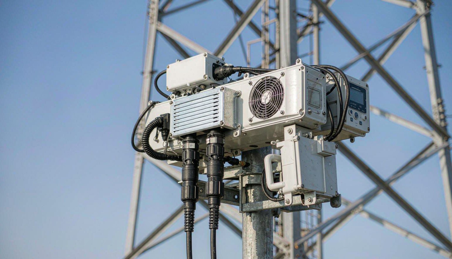
Why FTTA Jumpers Fail Before the Fiber Does
Glass is rarely the weak point on a tower. In field returns the majority of outdoor jumper faults trace back to the connector interface and the cable jacket rather than to the fiber core, and they cluster into four mechanisms:
- Water ingress at the coupling. A seal rated for the wrong mating geometry, or a shell that has been opened and re-mated without cleaning, lets moisture reach the ferrule. Loss creeps up over a wet season instead of failing outright.
- UV and ozone attack on the jacket. An indoor-grade PVC jacket left in direct sun for three or four summers will craze, crack and expose the strength members.
- Wind load and vibration at the connector body. RRU-mounted jumpers move constantly. Without strain relief and a service loop, every gust pulls on the ferrule assembly.
- Thermal cycling. Tower-top hardware sees roughly -40 °C to +85 °C across a year. Assemblies that were only qualified at room temperature drift in insertion loss.
For the purchase order, the useful framework is IEC 61753-1, which separates controlled-environment (category C) from uncontrolled-environment (category U) parts. An FTTA jumper is an uncontrolled-environment part and should be qualified as one. GR-326 covers connector reliability, while GR-1209-CORE and GR-1221-CORE set the passive-component tests most carriers and tower companies still reference.
| Failure mode | Root cause in the field | What to fix in the PO |
|---|---|---|
| Water in the ferrule | Seal damaged, or outer interface mated to the wrong port type | IP67 / IP68 coupling matched to the RRU port, plus an immersion test report |
| Jacket cracking | UV and ozone exposure beyond five years | LSZH or PE jacket with UV stabiliser, documented flame and UV rating |
| Intermittent high loss | Connector body loaded by wind, bend radius ignored at entry | Strain relief, stated minimum bend radius, cable-tie spacing in the install note |
| Loss creep across seasons | Ferrule and housing expand at different rates | Wide-temperature qualified assembly, -40 °C to +85 °C, GR-326 test data |
| Connector pull-out | Retention force never specified | Locking mechanism type plus a tensile load figure and mating-cycle count |
Matching the Hardened Interface to the Radio Port
ODVA, FullAXS, PDLC and NSN look similar in a catalogue photo and are not physically interchangeable. Even where the component inside the shell is a duplex LC in every case, the outer housing, the keying and the lock are different, and a shell that almost fits is the most expensive mistake in an FTTA order. Confirm the interface before anything else.
| Interface | Locking | Inner interface | Sealing | Common deployment |
|---|---|---|---|---|
| ODVA | Quarter-turn bayonet | LC duplex, SC simplex, MPO | IP67 / IP68 | Wide vendor base, industrial wireless, RRH |
| FullAXS | Bayonet, blind mate with one hand | LC duplex | IP67 | Tower-top RRU with direct transceiver access |
| PDLC | Push-pull bayonet | LC duplex | IP67 | Outdoor small cells, backhaul, RRU ports |
| NSN | Screw coupling, compact body | LC duplex | IP67 | Nokia / NSN radio portfolios |
| OptiTap / H-connector | Threaded | SC/APC simplex | IP68 | FTTH drop cable into MST terminals |
Because these families do not cross-mate, the cheapest protection against a wrong order is evidence. A photograph of the radio port, or one existing sample jumper from the site, settles the question in minutes. When an order spans several vendors’ radios, keep the internal connectors consistent as duplex LC across the site so spares and test equipment stay interchangeable, and let the shells differ.
Cable Construction Behind the Connector
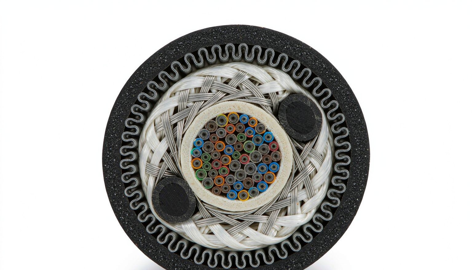
Once the interface is fixed, the next question is what the shell is attached to. Tower runs normally use a 5.0 mm or 7.0 mm outdoor cable with aramid yarn strength members and, where crush or rodent risk exists, corrugated steel armour, commonly ordered in GYFJH style. The fiber is almost always OS2 single-mode, and G.657.A1 is worth requesting because it tolerates the tight bend at the RRU entry better than a standard G.652.D core (ITU-T G.652 / G.657).
| Construction | Jacket | Strength member | Typical OD | Best for |
|---|---|---|---|---|
| Standard outdoor jumper | LSZH, UV stabilised | Aramid yarn | 5.0 mm | Tower-top RRU runs and short spans |
| Armored outdoor jumper | PE or LSZH over corrugated steel | Aramid yarn plus steel tape | 7.0 mm | Rooftop, duct, direct burial, rodent exposure |
| Hybrid power and fiber | LSZH | Aramid yarn | 7.0 – 12 mm | Sites where RRU power and fiber share one route |
Two numbers decide whether the assembly survives installation: the minimum bend radius under load and the maximum tensile figure the crew may pull to. Both belong on the drawing, not only in a datasheet. On the optical side, the same single-mode assemblies used for FTTA are also the ones used indoors at the BBU, which is why buyers often consolidate both ends of the link into one order.
Optical and Mechanical Values to Fix on the Purchase Order
Ask for insertion loss and return loss per mated pair at 1310 nm and 1550 nm, measured on the finished assembly rather than on loose components. Values we routinely commit to on outdoor FTTA assemblies:
- LC/UPC: IL ≤ 0.30 dB, RL ≥ 50 dB
- LC/APC: IL ≤ 0.30 dB, RL ≥ 60 dB
- MPO-12 low loss grade: IL ≤ 0.35 dB
- Measurement basis: IEC 61300-3-4, with the test wavelength and source type stated in the report
Then the mechanical block, which is where outdoor orders are usually weakest: IP rating together with the test method, operating temperature range, tensile load, crush resistance, minimum bend radius, mating cycles (500 is a reasonable floor for LC), and salt spray hours for coastal and offshore sites. ITU-T L.36 is a useful reference for single-mode connector requirements and points back to the IEC 61754 interface drawings.
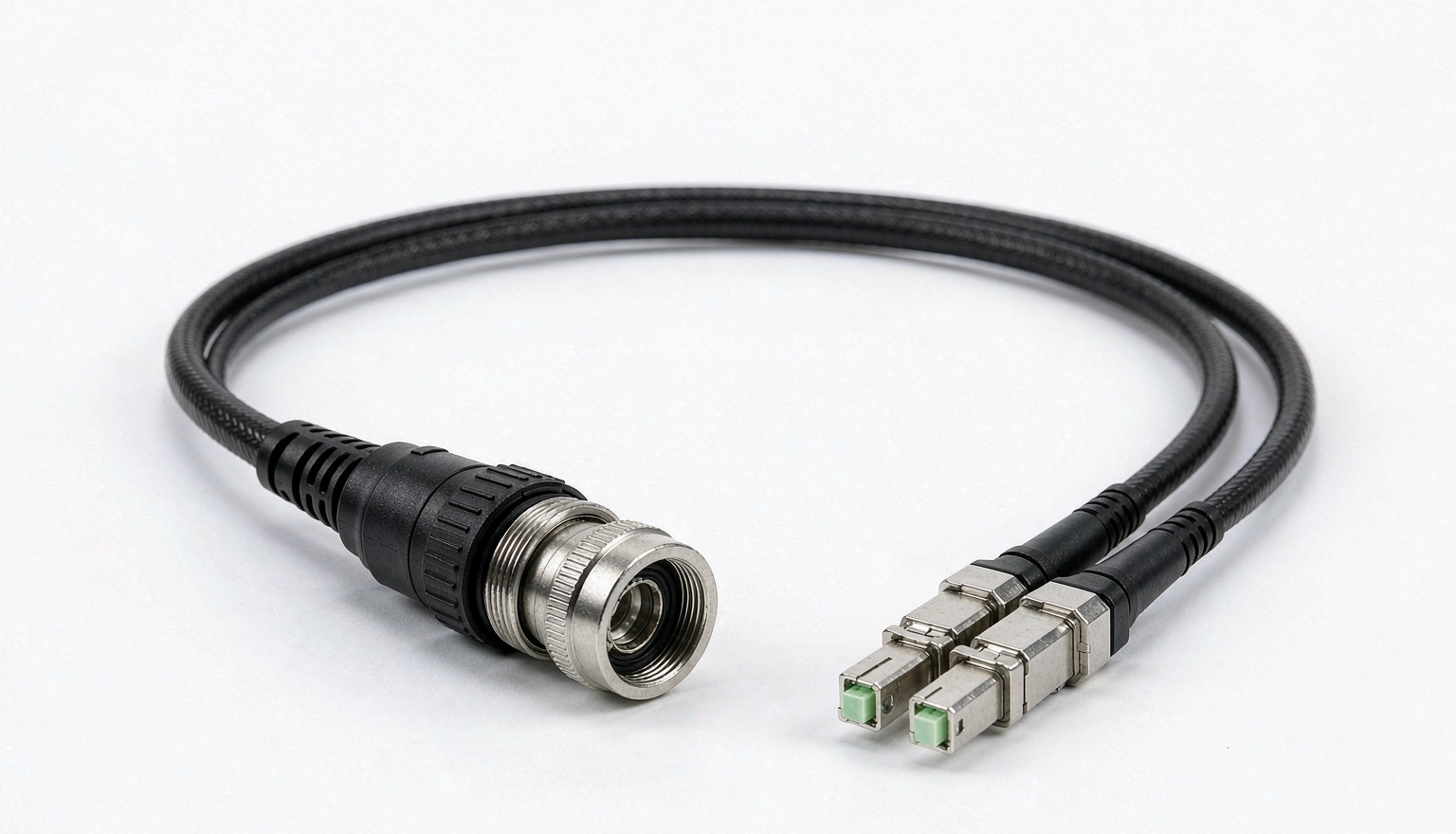
Run the loss numbers before the order is placed, not after. A 2-fiber CPRI or eCPRI run from the BBU to a tower-top radio typically crosses a patch panel, two connectors at each end and a splice or two, and the total has to stay inside the radio’s receive window. Our walkthrough of insertion loss budget calculation covers the arithmetic, and Fluke Networks publishes a matching reference for field test limits.
Run Lengths, Breakouts and Spares
Order length is where budgets leak quietly. Measure the installed route rather than the tower height: tower climb plus tray route plus a service loop long enough to reach the radio without tension. A tolerance of ±1 m or ±1 %, whichever is greater, is normal on outdoor assemblies, and fan-out lengths need their own figure when one end splits from a duplex LC into two simplex legs.
Keep the order tidy with a label scheme agreed in advance, dust caps fitted to every unmated end, and a small spare ratio. Two to three percent is enough for most sites; on remote or island projects, five percent is cheaper than an air freight shipment. For high-density towers where several radios share one route, a hardened MPO-based trunk with patch cord breakouts reduces the number of tower-top mates substantially.
Sealing Practice and Handover Checks
Most of the field failures we hear about were not manufacturing defects. They were a dusty connector pushed into a clean hardened shell. The handover routine that prevents this is short: inspect every end face under a scope, clean it, cap it, and only then mate. Check that the bayonet or screw coupling is fully seated, not merely finger tight, and that the cable is supported within the jacket rather than hanging from the connector.
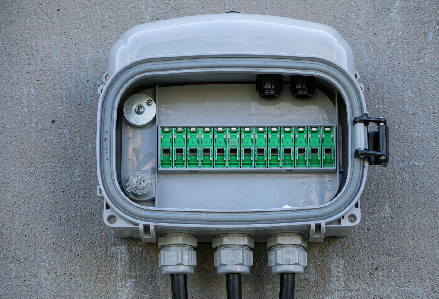
Where the tower run meets the outside plant, terminate into a pole- or wall-mounted fiber termination box rather than leaving a mated pair exposed. If the site is an FTTH drop rather than FTTA, the FOA connector identification tables are a quick way to confirm which family you are holding, and FOA loss budget notes help with the acceptance figures.
FTTA Jumper Specification Decision Tree
Work through these six steps in order and the specification writes itself:
- Read the radio port. ODVA, FullAXS, PDLC, NSN or OptiTap. Lock the outer interface before discussing anything else.
- Confirm the inner interface. Duplex LC for CPRI and eCPRI, SC simplex for single-channel sites, MPO for trunk consolidation.
- Set fiber and polish. OS2 G.657.A1 by default, UPC unless the radio specification calls for APC.
- Choose the cable. 5.0 mm for tower-top, 7.0 mm armoured for roof, duct, burial or rodent exposure.
- Write the numbers. IL and RL per mated pair, IP rating with test method, temperature range, tensile load, bend radius, mating cycles.
- Add the practical items. Route length with service loop, fan-out lengths, label scheme, dust caps, and a test report per reel.
Send us the port photograph and the route length and we will confirm the interface, the cable construction and the test values in the quotation, so the first order is the right order and the second climb is not a repeat visit.