
Use a cassette when conversion to duplex ports and protected internal routing are priorities, an adapter panel for direct MPO pass-through, and a harness when equipment ports need discrete connectors without a cassette. Choose from the service model and channel map, not rack appearance.
All three methods can connect an MPO trunk to equipment, but they place connections and polarity transitions in different locations. That changes loss allocation, cleaning access, spare strategy and the time needed to move a circuit. A comparison should count every optical interface and identify what technicians touch during routine work.
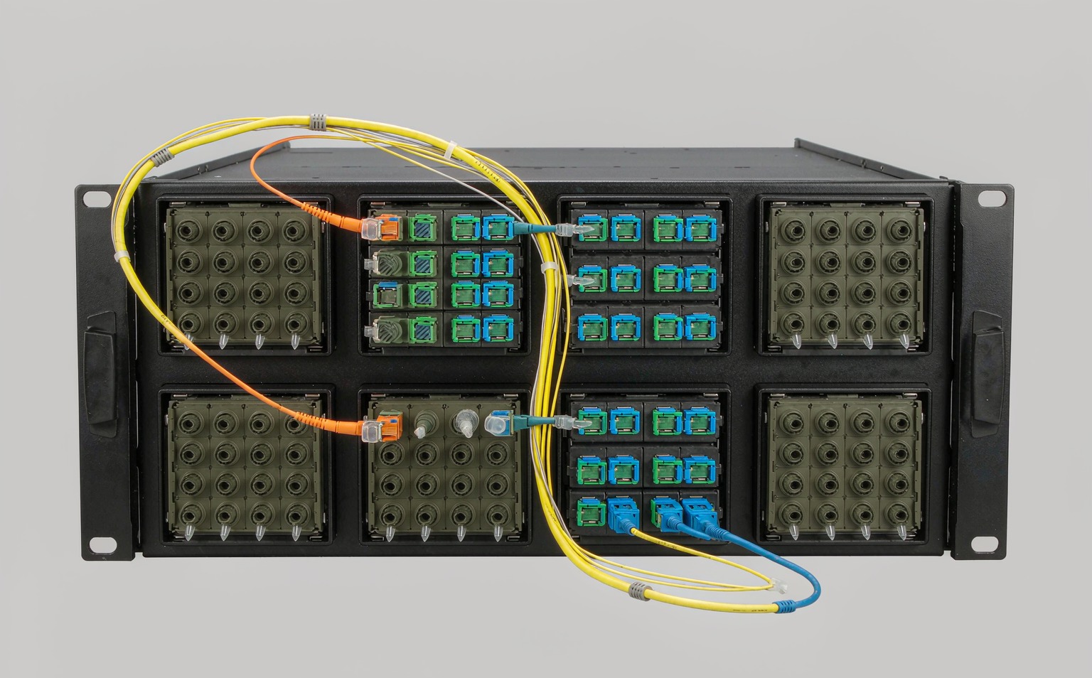
What Must Be Decided for MPO cassette vs adapter panel?
Use the decision table to turn the topic into controlled purchase, design and acceptance inputs. Each row should be confirmed against the actual equipment, route and destination standard rather than copied from a generic catalogue.
| Decision area | What to specify | Why it matters | Evidence to retain |
|---|---|---|---|
| Port presentation | LC duplex, direct MPO or discrete breakout connectors | Matches equipment and patching workflow | Front and rear port map |
| Connection count | Every mated pair in the channel | Consumes loss budget and cleaning time | Channel loss allocation |
| Polarity points | Trunk, module and harness transformations | Multiple transforms create errors | End-to-end polarity schedule |
| Service access | Which side technicians clean or replace | Affects outage scope | Maintenance procedure |
| Migration | Module swap, repatch or harness replacement | Controls future labour | Approved transition plan |
How to Control MPO cassette vs adapter panel in the Project
The controls below connect the drawing, sample, production lot and installed result. They are deliberately practical: each one produces a record that procurement, engineering and field teams can review later.
Count interfaces before buying hardware
Build the complete channel and count adapters, cassette internals and equipment connections. Compare loss and maintenance work on the same route.
Put polarity on one drawing
Do not distribute polarity assumptions across trunk, cassette and patch-cord datasheets. One channel schedule should show every position from transmitter to receiver.
Model moves and changes
Ask which component a technician touches when a port moves. A dense design is useful only when latches, labels, cleaning tools and spares remain accessible.
Pilot the migration state
Test both the opening configuration and the planned higher-speed configuration. This reveals modules or harnesses that strand fibres or reverse lanes later.
Acceptance and Handover Checks
Agree the method and disposition before testing begins. A result without a defined record owner or failure action is difficult to use during shipment release or commissioning.
| Check | Method | Record | Failure action |
|---|---|---|---|
| Channel map | Review every interface | Approved topology | Resolve missing positions |
| Loss allocation | Calculate and test full path | Budget and measured result | Reduce interfaces or improve components |
| Cleaning access | Use field tools on populated panel | Service trial | Change layout |
| Polarity | Test all lanes | Continuity report | Correct module or harness |
| Migration | Assemble target configuration | Pilot result | Revise component strategy |

Standards and Evidence to Put Behind the Purchase Order
This IEC procedure addresses attenuation, polarity and length testing for installed MPO-terminated cabling. See IEC 61280-4-5 MPO cabling test procedure.
The 2022 edition covers end-face debris, scratches and defects and states that visual inspection does not replace optical qualification. See IEC 61300-3-35 connector inspection.
The 2024 edition specifies inspection and testing of installed optical-fibre cabling. See ISO/IEC 14763-3:2024 optical cabling testing.
Procurement brief
Select cassette, panel or harness by the full operating workflow: ports, loss, polarity, access, spares and migration. The lowest component count is not always the lowest operating risk.
- Draw the complete channel
- Count and allocate every connection
- Verify cleaning and latch access
- Test all fibre positions
- Approve the migration configuration
For a project-specific quotation, review Fenxi’s MPO connector range, MPO/MTP patch cords, MPO trunk cable specification guide, and MPO polarity methods guide. Send the destination market, connector interfaces, fibre type, cable construction, quantities, drawing revision and required test records. The response can then separate standard catalogue options from items that need confirmation or custom tooling.