
Inspect every MPO face before mating, clean only with tools designed for the exact pinned or unpinned interface, then inspect again. The whole rectangular ferrule needs attention because debris outside one fibre can migrate across the array during mating.
MPO cleaning is harder than single-fibre cleaning because the ferrule has multiple cores, guide-pin features and a broad contact surface. A quick look at one fibre is not enough. The current IEC inspection standard explicitly addresses contamination across rectangular ferrules and treats visual inspection as an addition to optical testing, not a replacement.
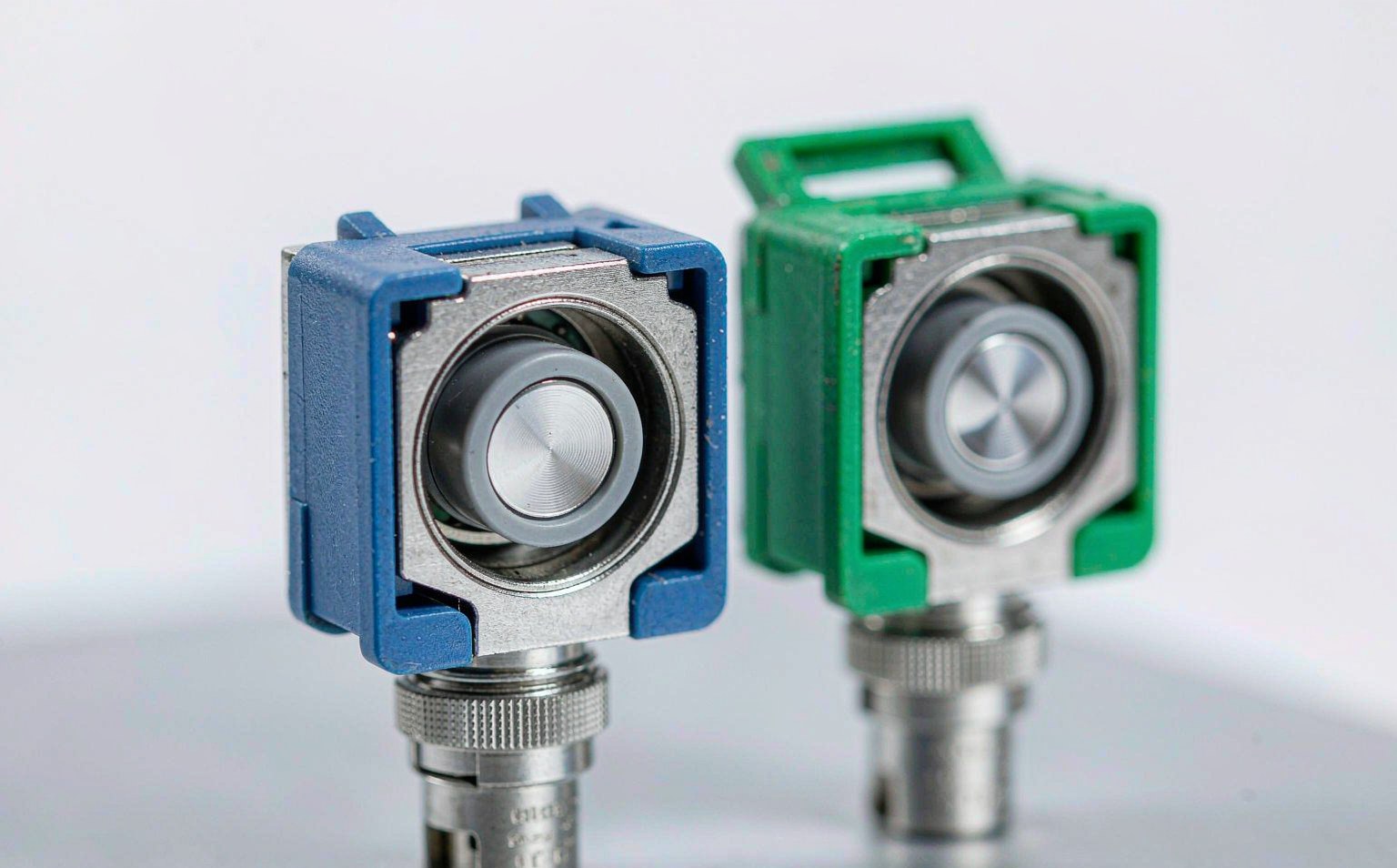
What Must Be Decided for MPO connector cleaning?
Use the decision table to turn the topic into controlled purchase, design and acceptance inputs. Each row should be confirmed against the actual equipment, route and destination standard rather than copied from a generic catalogue.
| Decision area | What to specify | Why it matters | Evidence to retain |
|---|---|---|---|
| Interface | Pinned or unpinned MPO and row count | Determines probe and cleaning tip | Tool compatibility list |
| Inspection area | Whole ferrule and every fibre position | Debris can migrate during mating | Saved full-face image |
| Cleaning method | Dry or approved wet-to-dry sequence | Wrong tools can leave residue | Work instruction |
| Reinspection | Mandatory after every cleaning attempt | Confirms debris was removed | Before-and-after images |
| Escalation | Maximum attempts and damage criteria | Stops endless cleaning of a damaged face | Disposition record |
How to Control MPO connector cleaning in the Project
The controls below connect the drawing, sample, production lot and installed result. They are deliberately practical: each one produces a record that procurement, engineering and field teams can review later.
Inspect both sides
A clean jumper will be contaminated by a dirty adapter or transceiver interface. Inspect every accessible mating face before connection and keep caps on cleaned parts.
Use the correct tip
Pinned and unpinned faces require compatible probe and cleaner geometry. Confirm the tool can reach the fibre array without striking guide pins.
Save the evidence
Store images with cable or port identity, date and operator. A green indicator without the image is weak evidence during a later incident review.
Separate contamination from damage
Cleaning can remove debris; it cannot repair scratches, pits or broken guide features. Escalate persistent defects to optical testing and component replacement.

Acceptance and Handover Checks
Agree the method and disposition before testing begins. A result without a defined record owner or failure action is difficult to use during shipment release or commissioning.
| Check | Method | Record | Failure action |
|---|---|---|---|
| Initial inspection | Capture full MPO face | Image and result | Clean or replace |
| Tool verification | Confirm correct pinned or unpinned tip | Tool ID | Stop incompatible tool |
| Post-clean inspection | Capture second image | Before-and-after pair | Repeat within approved limit |
| Optical test | Measure required lanes | Per-fibre result | Quarantine failed assembly |
| Cap and pack | Fit clean protective cap | Packaging check | Recap before storage |
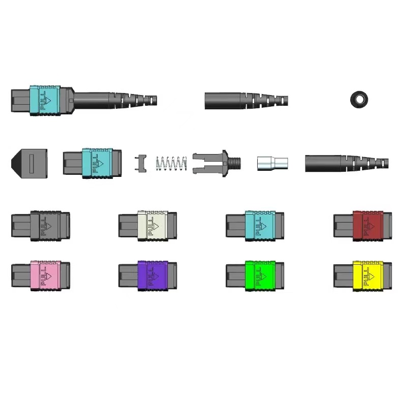
Standards and Evidence to Put Behind the Purchase Order
The 2022 edition covers end-face debris, scratches and defects and states that visual inspection does not replace optical qualification. See IEC 61300-3-35 connector inspection.
This IEC procedure addresses attenuation, polarity and length testing for installed MPO-terminated cabling. See IEC 61280-4-5 MPO cabling test procedure.
EXFO demonstrates inspection of an MPO connector with an automated inspection probe. See EXFO MPO inspection demonstration.
Video Demonstration
The demonstration below is included because it shows the same inspection or test task discussed in this article. Use it as a method reference, not as a substitute for the project specification or instrument manual.
Watch: EXFO MPO connector inspection demonstration
Field handover
The reliable rule is inspect, clean if necessary, inspect again and then test. Keep the image and lane results linked to the same connector identity.
- Identify MPO gender and rows
- Inspect the whole ferrule
- Use compatible tools
- Limit cleaning attempts
- Save images and optical data together
For a project-specific quotation, review Fenxi’s MPO connector range, MPO/MTP patch cords, MPO trunk cable specification guide, and MPO polarity methods guide. Send the destination market, connector interfaces, fibre type, cable construction, quantities, drawing revision and required test records. The response can then separate standard catalogue options from items that need confirmation or custom tooling.